Bayer HealthCare MEDRAD MRXperion Operation Manual
Mr injection system
Hide thumbs
Also See for MEDRAD MRXperion:
- Operating manual (98 pages) ,
- Instructions for use manual (87 pages) ,
- Operation manual (32 pages)
Table of Contents
Advertisement
Quick Links
Advertisement
Table of Contents

Related Manuals for Bayer HealthCare MEDRAD MRXperion


Summary of Contents for Bayer HealthCare MEDRAD MRXperion
- Page 1 Operation Manual...
- Page 3 Operation Manual The MEDRAD® MRXperion MR Injection System has an expected service life* of 7 years from the date of product installation when operated according to the instructions provided with this device. These 7 years include suggested or mandatory actions of preventative maintenance and repair activities, as well as required calibration(s) that are needed. Required reading includes the instructions for use and other materials provided with the device.
- Page 4 MEDRAD® MRXperion...
-
Page 5: Table Of Contents
Operation Manual 1 Introduction ......................1 1.1 Certifications....................................1 1.2 Indications For Use ..................................1 1.3 Training Information..................................1 1.4 Contraindications................................... 1 1.5 Restricted Sales ....................................1 1.6 Required Training ................................... 1 1.7 Disclaimers....................................... 1 2 Symbols........................3 2.1 Manufacturing Symbols ................................3 2.2 Shipper Symbols.................................... - Page 6 MEDRAD® MRXperion 6.2 Injector Head Components ................................31 6.2.1 Manual Knobs..................................31 7 System Lights and Indicators................33 7.1 Injector Head Lights and Indicators ............................33 7.2 Injector Status Lights...................................34 7.3 Workstation Power Indicators ..............................35 7.4 Handswitch Light ..................................35 8 Powering Up and Shutting Down the System ..........37 8.1 Powering Up the System................................37 8.2 Shutting Down the System ................................38 8.2.1 Hard Shutdown..................................38...
- Page 7 Operation Manual 12.5 Aborting an Injection ................................63 12.6 Viewing Injection Progress...............................63 12.7 Reminders ....................................64 13 Completing an Injection ..................65 13.1 Injection Complete ..................................65 13.2 Injection Aborted..................................66 13.3 Exiting Injection Complete ..............................67 13.3.1 Conducting Another Injection .............................67 14 Removing Disposable Syringes and Connector Tube ........69 14.1 Removing Disposable Syringes and Connector Tube......................69 15 Advanced Configurations ................71 15.1 System Setup ....................................71...
- Page 8 MEDRAD® MRXperion 17.4.1 Operational Checkout..............................94 17.5 Annually .......................................95 17.5.1 Injection System Calibration ............................95 17.5.2 Checking Electrical Leakage ............................95 18 Specifications....................97 18.1 Workstation Specifications ..............................97 18.1.1 Workstation Dimensions .............................97 18.1.2 Workstation Connections .............................98 18.1.3 Workstation Input Power Requirements ........................98 18.2 Workstation with Pod Specifications ............................99 18.2.1 Workstation with Pod Dimensions and Weight......................99 18.2.2 Workstation with Pod, Pod Connections ........................99 18.2.3 Workstation with Pod, Display Connections ......................
- Page 9 Operation Manual 19.8 Scan Room DC Power Cables..............................110 19.9 Prefilled Syringe Adapters (PFA) ............................110 20 Compliance to IEC 60601-1-2 / 2nd, 3rd, and 4th Editions ......111...
- Page 10 MEDRAD® MRXperion...
-
Page 11: Introduction
Operation Manual 1 - 1 Introduction This manual applies to the MEDRAD® MRXperion MR Injection System, referred to as the system throughout this document, Catalog Number: MRXP 200. Read all of the information contained in this manual. Understanding this information will assist users in operating the system in a safe manner. - Page 12 1 - 2 MEDRAD® MRXperion certified to either IEC 60601-1 (Operator or Patient Environment Use) or, outside the patient environment, the level of safety must be equivalent to equipment complying with their respective IEC or ISO safety standards, e.g. IEC 62368-1 or IEC 60950- 1 (Operator Environment Use Only), and must comply with the relevant requirements according to IEC 60601-1.
-
Page 13: Symbols
Operation Manual 2 - 3 Symbols "Manufacturing Symbols" "Shipper Symbols" "Notified Body" "Regulatory Classifications" "MR Icons and Classifications" "Warning Labels and Symbols" 2.1 Manufacturing Symbols Manufacturer (ISO 15223-1, 5.1.1) Authorized representative in the European community (ISO 15223-1, 5.1.2) Date of Manufacture (ISO 15223-1, 5.1.3) 2.2 Shipper Symbols Temperature range (ISO 15223-1, 5.3.7) Humidity range (ISO 15223-1, 5.3.8) -
Page 14: Notified Body
2 - 4 MEDRAD® MRXperion Keep dry (ISO 15223-1, 5.3.4) Fragile, handle with care (ISO 15223-1, 5.3.1) Part Number Net Weight (ISO 7000, 1321B) Quantity (IEC TR 60878, 2794) 2.3 Notified Body Indicates that this device conforms to the requirements of the European Union Medical Device Regulation 2017/745 2.4 Regulatory Classifications Identifies a type BF applied part complying with IEC 60601-1 standards... - Page 15 Operation Manual 2 - 5 Indicates separate collection for Electrical and Electronic Equipment per Directive 2002/96/EC. Refer to the following website for additional information: www.weee.bayer.com Indicates that this product contains certain toxic or hazardous substances or elements and can be used safely during its environmental protection use period, indicated by the number in the center of the logo.
-
Page 16: Mr Icons And Classifications
2 - 6 MEDRAD® MRXperion Identifies an input terminal. (IEC TR 60878, 5034) Identifies an output terminal. (IEC TR 60878, 5034) Identifies service assistance. (IEC TR 60878, 0717) 2.5 MR Icons and Classifications Has been demonstrated to pose no known hazards in a specified MR environment MR Conditional with specified conditions of use as defined by the ASTM International Standards for MRI Device Marking. - Page 17 Operation Manual 2 - 7 Caution: Transportable Weight- 43.4kg Safe Working Load- 0.75kg Warning: Refer to warnings and cautions on Instructions for Use packaged in each carton. (ISO 7010, W001) Attention: Refer to warnings and cautions on Instructions for Use packaged in each carton.
- Page 18 2 - 8 MEDRAD® MRXperion...
-
Page 19: Warnings, Cautions, And Notices
Operation Manual 3 - 9 Warnings, Cautions, and Notices "Warnings" "Cautions" "Notices" 3.1 Warnings WARNINGS Air Embolism Hazard - Serious patient injury or death may result. Use only disposables supplied by Bayer. Refer to "Section 19.2 - MEDRAD® MRXperion MR Injection System Syringe Kits". -
Page 20: Cautions
3 - 10 MEDRAD® MRXperion WARNINGS Patient and/or worker injury or equipment damage may result. The workstation (control room unit) is MR unsafe and is not for use in the scan room. The workstation is a known threat or poses a hazard in all MR environments as defined by the ASTM International Standards for MRI Device Marketing. -
Page 21: Notices
Operation Manual 3 - 11 3.3 Notices NOTICE Electro-Mechanical Hazard - Equipment Damage may result. Do not use the system immediately after it has been brought indoors from extreme outside temperatures. Allow the system to stabilize at room temperature before use. Condensation may cause electrical damage to the injection system. - Page 22 3 - 12 MEDRAD® MRXperion...
-
Page 23: System Overview
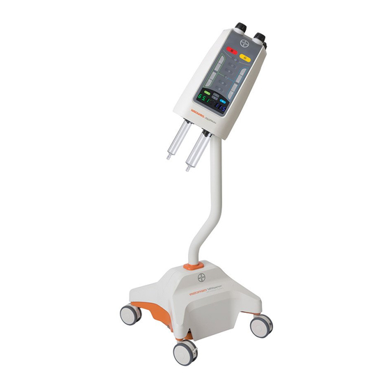
Operation Manual 4 - 13 System Overview "System Diagram" "Moving the System" "Fluid Delivery Basics" "Syringe Installation Features" "Basic Informatics" "Programming Mode" "Using the Pedestal with Integrated IV Pole" WARNING Patient and/or worker injury or equipment damage may result. The workstation (control room unit) is MR unsafe and is not for use in the scan room. The workstation is a known threat or poses a hazard in all MR environments as defined by the ASTM International Standards for MRI Device Marketing. - Page 24 4 - 14 MEDRAD® MRXperion Figure 4 - 1: System Diagram - Power Supply in Scanner Room Scan Room Control Room 1 - Scan Room Unit (Injector) 6 - Control Room Unit (Workstation) 2 - Power Cable 7 - Workstation Power Supply 3 - Scan Room Unit Power Supply 8 - Fiber Optic Communication Link 4 - Fiber Optic Communication Link...
-
Page 25: Moving The System
Operation Manual 4 - 15 Figure 4 - 2: System Diagram - Power Supply Outside Scanner Room Scan Room Control Room and MRI Equipment Room 1 - Scan Room Unit (Injector) 6 - Penetration Panel Filter 2 - Power Cable 7 - Scan Room Unit Power Supply 3 - Fiber Optic Communication Link 8 - Workstation Power Supply... -
Page 26: Fluid Delivery Basics
4 - 16 MEDRAD® MRXperion Prior to moving the system, ensure that: the patient is disconnected the injector head is sitting above the base of the system there are no fluid containers attached Once the injector head column is in place, move the system by holding the handle or by holding the pedestal below the point indicated by the label on the pedestal arm. -
Page 27: I Checked For Air
Operation Manual 4 - 17 There are three types of phases: Fluid Delivery Phase: Defines the flow rate, volume, and duration of a fluid to be injected. Pause Phase: Defines a set amount of time that fluid injection will be paused. The next phase will execute once the set time has elapsed. -
Page 28: Fluid Pressure And Pressure Limiting
4 - 18 MEDRAD® MRXperion 4.3.7 Fluid Pressure and Pressure Limiting The fluid pressure is measured by the system during the execution of a phase and ensures the protocol Pressure Limit is not exceeded. Fluid pressure is dependent on the following: Flow rate Fluid viscosity Fluid temperatures... -
Page 29: Basic Informatics
Operation Manual 4 - 19 Auto Docking: When Auto Advance is configured to be ON and a new empty syringe is installed, the injector piston automatically advances and docks with the syringe plunger. Auto Advance: When Auto Advance is configured to be ON and a new empty syringe is installed on the injector head, the piston automatically docks with the syringe plunger and advances it to the full forward position. - Page 30 4 - 20 MEDRAD® MRXperion...
-
Page 31: Understanding The Display And Workstation
Operation Manual 5 - 21 Understanding the Display and Workstation "Home Screen" "Workstation Descriptions" 5.1 Home Screen Figure 5 - 1: Home Screen Name Icon (if applicable) Description Shows the volume in the syringes. An outline of the syringe displays if no syringe is present. Syringe Volume Information If applicable, a dotted line displays on the syringe graphic to indicate... - Page 32 5 - 22 MEDRAD® MRXperion Name Icon (if applicable) Description Date and Time Shows the current date and time. Reset Resets the protocol to the default factory values. Displays the total programmed volume per syringe or the total Total Volume combined volume in both syringes.
- Page 33 Operation Manual 5 - 23 Name Icon Description Injector Illuminates yellow when in active communication with injector head. Communicator I Checked for Air Illuminates yellow when the operator has confirmed that the Indicator syringes and tubing have been inspected for the presence of air. Figure 5 - 3: Protocol Manager Name Description...
- Page 34 5 - 24 MEDRAD® MRXperion Figure 5 - 4: Launch Menu Name Description Accesses the Setup options. Refer to "Chapter 15 - Advanced Configurations" for more Setup information. Accesses the eGFR and Weight-Based Dosing calculators. Calculator button will only Calculators appear in the Launch Menu if one or more calculators are enabled.
-
Page 35: Workstation Descriptions
Operation Manual 5 - 25 5.2 Workstation Descriptions NOTE: Two models of the Certegra® Workstation can operate with the system. Buttons and icons will differ slightly with each model. 5.2.1 Workstation Buttons and Icons Figure 5 - 5: Workstation, Front View Name Button/Icon Description... - Page 36 5 - 26 MEDRAD® MRXperion Figure 5 - 6: Workstation, Rear and Side Port View Icon Description Icon Description Identifies power input and supply Identifies computer network connection. connection. Identifies USB connections. Port 4, Identifies connection for screen identified with yellow outline, extension or transfer to a second always remains on.
-
Page 37: Workstation With Pod Buttons And Icons
Operation Manual 5 - 27 5.2.2 Workstation with Pod Buttons and Icons Figure 5 - 7: Workstation with Pod NOTE: Pod and display connection icons are not shown. Refer to "Section 18.2.2 - Workstation with Pod, Pod Connections" "Section 18.2.3 - Workstation with Pod, Display Connections" for more information. - Page 38 5 - 28 MEDRAD® MRXperion...
-
Page 39: Understanding The Injector Head
Operation Manual 6 - 29 Understanding the Injector Head "Injector Head Controls" "Injector Head Components" 6.1 Injector Head Controls NOTE: For more detailed information about injector head button light functionality, refer to "Section - 7.1 - Injector Head Lights and Indicators". - Page 40 6 - 30 MEDRAD® MRXperion Name Icon (if applicable) Description Volume Indicator Syringe not present: Displays dashes. (Side A or B) Syringe present: Indicates the volume loaded in the syringe. Double press with injector head pointed upward: Fills Syringe B (Saline) to the displayed volume (Auto Fill).
-
Page 41: Injector Head Components
Operation Manual 6 - 31 Name Icon (if applicable) Description When pressed, initiates a test injection based on operator-defined parameters. When blinking, indicates that the operator can perform a test inject to determine patency of the patient connection. Test Inject The head must be oriented with the syringes pointed downward and the I Checked For Air must be confirmed to use this function. - Page 42 6 - 32 MEDRAD® MRXperion...
-
Page 43: System Lights And Indicators
Operation Manual 7 - 33 System Lights and Indicators "Injector Head Lights and Indicators" "Injector Status Lights" "Workstation Power Indicators" "Handswitch Light" 7.1 Injector Head Lights and Indicators The buttons on the injector head illuminate or blink depending on the conditions listed below: Name Button / Icon Behavior / Event... -
Page 44: Injector Status Lights
7 - 34 MEDRAD® MRXperion Name Button / Icon Behavior / Event Displays “--” when no syringe is installed Displays “--” when syringe is engaged, plunger not docked Volume Display Displays actual volume when I Checked for Air confirmed, syringe engaged, plunger docked For key presses that the system is programmed to ignore, displays “--”... -
Page 45: Workstation Power Indicators
Operation Manual 7 - 35 7.3 Workstation Power Indicators Name Button / Icon Behavior / Event Not illuminated when Workstation is not connected to a power source Workstation Power Continuously illuminates amber during Full System Shutdown Indicator Continuously illuminates green when full system is ON Blinks green during Injector Shutdown Not illuminated when Workstation with Pod is not connected to a power source... - Page 46 7 - 36 MEDRAD® MRXperion...
-
Page 47: Powering Up And Shutting Down The System
Operation Manual 8 - 37 Powering Up and Shutting Down the System "Powering Up the System" "Shutting Down the System" "Restore from Injector Shutdown" "Restore from System Shutdown" 8.1 Powering Up the System CAUTION Electric Shock Hazard - Minor or moderate patient and/or worker injury may result. Verify that the voltage and frequency as labeled matches the voltage and frequency of the electrical outlet. -
Page 48: Shutting Down The System
8 - 38 MEDRAD® MRXperion 8.2 Shutting Down the System The system provides three options for shutting down the system: Full System Shutdown, Injector Shutdown, and System Restart. From the Launch menu, select Shutdown, and then select a shutdown option or press the power button on the workstation. -
Page 49: Calculators
Operation Manual 9 - 39 Calculators "Enabling Calculators" "Calculator Setup" "Using the Calculators" The system includes two calculators that can be used for determining weight-based dosing values and eGFR values. CAUTION Minor or moderate patient and/or worker injury may result. eGFR values are estimates. -
Page 50: Setting Up The Egfr Calculator
9 - 40 MEDRAD® MRXperion Figure 9 - 1: Accessing Calculator Setup from the Setup menu. The calculator setup can also be accessed from the Setup button on the Calculator screen. From the launch menu, select Calculator (1). Select the Setup button (2). Figure 9 - 2: Accessing Calculator Setup from the Calculator screen 9.2.1 Setting Up the eGFR Calculator Access the eGFR Calculator Setup by selecting the eGFR tab (1) on the Calculator Setup screen. - Page 51 Operation Manual 9 - 41 9.2.1.1 Enabling eGFR Formulas Check the box next to a formula name to enable it (3). Figure 9 - 3: Enabling eGFR Formulas NOTE: eGFR formulas have known limitations. Adhere to site policy and guidelines for proper use of these formulas.
- Page 52 9 - 42 MEDRAD® MRXperion NOTE: MDRD, Cockroft-Gault, Modified Cockroft-Gault, and CKD-EPI calculators are intended to be used only for adults age 18 years or older. Bedside Schwartz is intended to be used only for children under 18 years of age.
- Page 53 Operation Manual 9 - 43 9.2.1.2 Display Output Range Setup - Optional The system provides three options for configuring the eGFR display: No ranges Ranges without colors Ranges with system-assigned colors NOTE: There are no default range settings for the Cockcroft-Gault formula. All other formulas have the default setting of 0 to 30 ml/min/1.73 m for Range 1.
-
Page 54: Setting Up The Weight-Based Dosing Calculator
9 - 44 MEDRAD® MRXperion When maximum values have been assigned to all ranges, select OK to save and return to the Calculator Setup screen. Select OK on the Calculator Setup screen to save changes and return to the previous screen. 9.2.2 Setting Up the Weight-Based Dosing Calculator Figure 9 - 7: Defining Dosing Unit - Weight-Based Dosing Calculator Access the Weight-Based Dosing Calculator setup by selecting the Weight-Based tab (1) on the Calculator Setup... -
Page 55: Using The Egfr Calculator
Operation Manual 9 - 45 9.3.1 Using the eGFR Calculator NOTE: The eGFR calculator feature provided on this system is intended to be a point-of-care application. Adhere to site policy and guidelines when using the calculator feature. Figure 9 - 8: Using the eGFR Calculator Select Choose Formula (1) to choose a formula to use for the calculation. -
Page 56: Using The Weight Based Dosing Calculator
9 - 46 MEDRAD® MRXperion 9.3.2 Using the Weight Based Dosing Calculator NOTE: The calculated Weight Based Dose value is for reference and is not automatically reflected in the programmed protocol. The application of the calculated volume is at the operator’s discretion. NOTE: One or more contrast types must be saved before using the Weight Based Dosing calculator. -
Page 57: Protocol Management
Operation Manual 10 - 47 Protocol Management "Create or Edit a Protocol" "Save a Protocol" "Recall a Saved Protocol" WARNING Blood Vessel Hazard - Serious patient injury may result. Ensure that the programmed flow rate meets facility guidelines. Refer to "Section 18.9.2 - Maximum Flow Rate Performance". - Page 58 10 - 48 MEDRAD® MRXperion Select two of the three parameters (3) (refer to "Section 15.4.1 - Fluid Delivery Setup Configurable Items" for more information) and enter the values using the keypad(4). The third parameter will be calculated automatically. Figure 10 - 2: Enter Parameters Select Enter to confirm the entered value or select Cancel to disregard.
- Page 59 Operation Manual 10 - 49 Optionally, set or modify a reminder. Reminders are alerts that display after an operator-defined amount of time. The system stores reminders as part of the protocol. Select Reminders (1) from the Home Screen. Figure 10 - 4: Enter Reminders b.
-
Page 60: Save A Protocol
10 - 50 MEDRAD® MRXperion To define or modify the Test Inject parameters: Select Test Inject (1). Figure 10 - 5: Edit Test Inject Parameters b. Check the Enable box (2) to enable the test injection function. Select the parameter (3) to be automatically calculated. d. -
Page 61: Recall A Saved Protocol
Operation Manual 10 - 51 10.3 Recall a Saved Protocol Select Protocol Manager from the Home Screen. Select the desired region or select View All (1). Select the protocol name (2). Select OK (3). The Home screen displays the selected protocol. Figure 10 - 7: Recall Protocol To edit the protocol, refer to "Section 10.1 - Create or Edit a... - Page 62 10 - 52 MEDRAD® MRXperion...
-
Page 63: Preparing For Injection
Operation Manual 11 - 53 Preparing for Injection "Control Room Preparation" "Scan Room Preparation" 11.1 Control Room Preparation WARNING Blood Vessel Hazard - Serious patient injury may result. Ensure that the programmed flow rate meets facility guidelines. Refer to "Section 18.9.2 - Maximum Flow Rate Performance". - Page 64 11 - 54 MEDRAD® MRXperion WARNINGS Biological Contamination Hazard - Serious patient and/or worker injury or death may result. Properly discard contrast and saline containers and disposable items after use (refer to disposable label for specifics), or if there is any possibility that contamination may have occurred.
-
Page 65: Installing A Syringe
Operation Manual 11 - 55 The disposables tray is designed to fit in the handle of the injector for your convenience. If desired, place the tray in the handle as shown below while installing the syringe and connector tubing or to collect priming waste. 11.2.1 Installing a Syringe NOTICE Mechanical Hazard - Equipment damage may result. - Page 66 11 - 56 MEDRAD® MRXperion Install the spike on the corresponding syringe, then insert the spike into the correct fluid source. Refer to the fluid manufacturer's instructions for use and/or package insert. NOTE: The system has the capability of supporting up to a 150mL bag of saline and a single patient dose contrast bottle for hands-free fluid preparation.
-
Page 67: Attach And Prime The Tubing
Operation Manual 11 - 57 Remove the spike and discard the fluid source containers and spikes. Connect the disposable connector tube as outlined in "Section 11.2.3 - Attach and Prime the Tubing". 11.2.3 Attach and Prime the Tubing NOTICE Mechanical Hazard - Equipment damage may result. Do not install syringes and connector tube with excessive force. - Page 68 11 - 58 MEDRAD® MRXperion CAUTION Do not move the injector with the patient connected. Minor or moderate patient and/or worker injury may result. NOTE: If required, turn the manual knobs to remove any remaining air before connecting to the patient. Position the injector near the scanner table.
-
Page 69: Arming And Injecting
Operation Manual 12 - 59 Arming and Injecting "Add Volume Indicator" "Arming the Injector" "Initiating an Injection" "Operator Initiated Hold" "Aborting an Injection" "Viewing Injection Progress" "Reminders" NOTE: Verify that the protocol is correct prior to locking the protocol. 12.1 Add Volume Indicator Whenever the total volume programmed to be injected is greater than the volume remaining in the syringes, the Home Screen provides on-screen Add Volume indicators to communicate how much fluid should be added to perform the protocol. - Page 70 12 - 60 MEDRAD® MRXperion Figure 12 - 2: Arming Prevented Communication After examining the fluid path to determine it is free from excess air, perform the I Checked for Air Confirmation: Figure 12 - 3: I Checked for Air Confirmation Select Yes to acknowledge that the operator has examined the syringes and connector tubing and has determined that all air has been expelled.
-
Page 71: Arming From The Scan Room
Operation Manual 12 - 61 An operator selects Disarm on the display. An operator presses the Abort button on the injector head or the workstation. An operator activates any injector head controls other than Start/Hold or KVO. The injector head is moved to the upright position. An injection has completed. -
Page 72: Starting Kvo (Optional)
12 - 62 MEDRAD® MRXperion NOTE: To configure Test Inject parameters, refer to "page 10 - 49" 12.2.3 Starting KVO (Optional) If enabled, KVO can be initiated prior to initiating the injection. (For information about setting the KVO interval or disabling KVO, refer to "Section 15.4.1 - Fluid Delivery Setup Configurable Items".) It will function during Pause and/or Hold periods. -
Page 73: Operator Initiated Hold
Operation Manual 12 - 63 NOTE: Refer to "Chapter 7 - System Lights and Indicators" for a description of how the system lights function while armed, injecting, and/or during a hold. NOTE: If the protocol contains a Hold phase, the system holds the injection until the operator presses Start/Hold on the injector head, workstation, or handswitch to resume the protocol. -
Page 74: Reminders
12 - 64 MEDRAD® MRXperion Indicators of Start of Shows the start of each phase. Phase Injection Information Displays the current phase information during the injection. Illuminated blue to indicate when KVO is activated. Press at any time during the KVO Button injection to end KVO. -
Page 75: Completing An Injection
Operation Manual 13 - 65 Completing an Injection "Injection Complete" "Injection Aborted" "Exiting Injection Complete" 13.1 Injection Complete When an injection completes: The Injection Completed screen displays a summary of the injection and the total fluid delivered. The elapsed time of the injection continues to increment until an operator exits the Injection Completed screen. KVO, if activated (the KVO button will be illuminated blue), continues to dispense small boluses of saline until the operator stops KVO or until no fluid remains in Syringe B. -
Page 76: Injection Aborted
13 - 66 MEDRAD® MRXperion Select the Graph button to view a graphical representations of the injection. Figure 13 - 2: Injection Complete - Graph Select the left or right arrow (1) to scroll through the injection history. (If the entire injection history fits within the graph, no arrows will appear.) A graphical representation (2) of the phases and pressure limits of the completed injection is displayed until the Injection Complete screen is exited. -
Page 77: Exiting Injection Complete
Operation Manual 13 - 67 13.3 Exiting Injection Complete 13.3.1 Conducting Another Injection NOTE: Depending on how Fluid Delivery Setup is configured, the protocol may reset after the injection. The default setting is for the system to keep the previous protocol for the next injection. Select Same Patient. - Page 78 13 - 68 MEDRAD® MRXperion...
-
Page 79: Removing Disposable Syringes And Connector Tube
Operation Manual 14 - 69 Removing Disposable Syringes and Connector Tube 14.1 Removing Disposable Syringes and Connector Tube WARNING Biological Contamination Hazard - Serious patient and/or worker injury or death may result. Properly discard contrast and saline containers and disposable items after use (refer to disposable label for specifics), or if there is any possibility that contamination may have occurred. - Page 80 14 - 70 MEDRAD® MRXperion...
-
Page 81: Advanced Configurations
Operation Manual 15 - 71 Advanced Configurations "System Setup" "Calculator Setup" "Protocol Manager Setup" "Fluid Delivery Setup" "Help" "Fluid A" 15.1 System Setup System Setup enables the operator to configure settings that affect operation of the overall system. From the launch menu, select Setup, then select System Setup. Figure 15 - 1: Setup Categories (System Setup) Select a System Setup option or toggle to the next screen for additional options. -
Page 82: System Setup Configurable Items
15 - 72 MEDRAD® MRXperion Set the parameter for the selected option. Figure 15 - 3: Option Parameters for Display Audio Level - System Setup Select OK. Select Yes to confirm and save the changes. 15.1.1 System Setup Configurable Items Configurable Item Description Language... -
Page 83: Protocol Manager Setup
Operation Manual 15 - 73 15.3 Protocol Manager Setup Protocol Manager Setup enables the operator to manage the organization and display of protocols that are stored in the Protocol Manager. To create or edit a protocol, refer to "Section 10.1 - Create or Edit a Protocol". -
Page 84: Rearrange Protocol List
15 - 74 MEDRAD® MRXperion 15.3.2 Rearrange Protocol List Go to SETUP > PROTOCOL MANAGER SETUP and select the protocol to move. Select Move Up or Move Down. Figure 15 - 6: Rearrange Protocol List 15.3.3 Move Protocol to a New Region Go to SETUP >... -
Page 85: Rename A Region
Operation Manual 15 - 75 15.3.5 Rename a Region Go to SETUP > PROTOCOL MANAGER SETUP and select the region to rename. Select RENAME. Figure 15 - 8: Rename a Region Enter the name using the keyboard that pops up, and select Enter. Select OK, then select Yes on the confirmation window to save changes. - Page 86 15 - 76 MEDRAD® MRXperion Select a Fluid Delivery Setup option (1) or toggle to the next screen for additional options (2). Figure 15 - 10: Setup Screen (Fluid Delivery Setup) Set the parameter for the selected option. Figure 15 - 11: Option Parameters (Fluid Delivery Setup) Select OK.
-
Page 87: Fluid Delivery Setup Configurable Items
Operation Manual 15 - 77 15.4.1 Fluid Delivery Setup Configurable Items Configurable Item Description Sets the syringe to be used for priming the tubing. Select A to configure Syringe A (contrast) to Priming Source be the priming source. Select B to configure Syringe B (saline) to be the priming source. Enable or disable test injection. - Page 88 15 - 78 MEDRAD® MRXperion Edit information for each of the following items by selecting a tab (2) on the left of the screen and entering the parameters: Figure 15 - 12: Adding a New Contrast Type Contrast Name: Select an existing contrast name from the list (3) or add a new contrast name by selecting Add New (4) and entering the name of the contrast using the keyboard window that will appear on the display.
- Page 89 Operation Manual 15 - 79 Select OK to save all changes and exit Contrast Configuration. 15.4.2.2 Editing an Existing Contrast Type NOTE: When using the Weight Based Dosing Calculator, if the operator changes the dose, the new dose will be used for the calculation only and will not affect the labeled dose saved with the contrast type.
-
Page 90: Help
15 - 80 MEDRAD® MRXperion Figure 15 - 14: Editing an Existing Contrast Type 15.4.2.3 Contrast Type Management When two or more contrast types have been saved, the order can be changed by using the Move Up and Move Down buttons on the Contrast Configuration screen. -
Page 91: Fluid A
Operation Manual 15 - 81 Figure 15 - 16: Help System Navigation 15.6 Fluid A When selected, Fluid A displays the most recent Fluid A values entered. Press OK to select again or Cancel to choose new values. Refer to the Certegra® Applications and Workstation Accessories manual. Figure 15 - 17: Fluid A Value Selection... - Page 92 15 - 82 MEDRAD® MRXperion...
-
Page 93: System Messages
Operation Manual 16 - 83 System Messages The system will display messages on the screen as conditions or events occur. There are three types of basic messages: Type 1 messages Type 2 messages Type 3 messages 16.1 Type 1 Messages Type 1 messages provide information regarding the current system status and will clear automatically. -
Page 94: Type 3 Messages
16 - 84 MEDRAD® MRXperion 16.3 Type 3 Messages WARNING Patient injury may result from a system malfunction. If a system malfunction occurs, immediately disconnect the patient from the system. If a fault message is displayed that cannot be corrected and/or the system is not operating correctly, do not use the injection system. -
Page 95: Cleaning And Maintenance
Operation Manual 17 - 85 Cleaning and Maintenance "In the Case of Saline or Contrast Media Spills" "Daily and In the Case of Visible Contamination" "Daily" "Monthly" "Annually" WARNINGS Electro-Mechanical Hazard - Serious injury or death may result from exposure to hazardous voltages existing within the system. -
Page 96: In The Case Of Saline Or Contrast Media Spills
17 - 86 MEDRAD® MRXperion 17.1 In the Case of Saline or Contrast Media Spills NOTICE: Electro-Mechanical Hazard - Equipment Damage may result. Do not use cleaning agents containing quaternary ammonium compounds (e.g. dimethyl ethylbenzyl ammonium chloride), such as Sani-Cloth, CaviWipes, and ZEP brand cleaners, and/or ethyl alcohol, such as Lysol and Clorox on the syringe piston or syringe interface. -
Page 97: Daily And In The Case Of Visible Contamination
Operation Manual 17 - 87 Turn off power to the injector. Clean the injector head surfaces (excluding pistons and syringe interface, refer to Figure 17 - 3: Syringe Piston) with a clean, soft, non-linting wipe dampened with warm water (wet but not dripping) for a minimum of 1 minute and until visibly clean. -
Page 98: Disinfecting The Injector Head
17 - 88 MEDRAD® MRXperion Frequency: Daily and in the case of visible contamination Materials: Clean, soft, non-linting wipe Warm water Cleaning agent: Use either Sani-Cloth® Plus Germicidal Disposable Cloth (EPA registration # 9480-6) or CaviWipes™ Disinfect- ing Towelettes (EPA registration # 46781-8) within the United States, except as noted above. Use either Sani-Cloth®... -
Page 99: Daily
Operation Manual 17 - 89 NOTE: If in a country where Sani-Cloth Plus or CaviWipes are not available, and using an equivalent disinfecting agent (refer to the materials listed above), follow the same instructions specified in step 2. Using Sani-Cloth Plus or CaviWipes, allow surfaces to remain visibly wet for 3 minutes. If needed, use additional wipes to ensure the surfaces remain wet for the full duration. -
Page 100: Cleaning The Pistons And Syringe Interface
17 - 90 MEDRAD® MRXperion 17.3.3 Cleaning the Pistons and Syringe Interface NOTICE: Electro-Mechanical Hazard - Equipment Damage may result. Do not use cleaning agents containing quaternary ammonium compounds such as Sani-Cloth Plus, CaviWipes and/or ethyl alcohol such as Lysol on the syringe piston or syringe interface. Frequency: Daily 17.3.3.1 Pistons Figure 17 - 3: Syringe Piston... - Page 101 Operation Manual 17 - 91 17.3.3.2 Syringe Interface Figure 17 - 4: Syringe Interface (1) and Syringe Sensing Window (2) Materials: Clean, soft, non-linting wipe Cotton swab Warm water Turn on the power to the injector. Fully retract both pistons using the reverse piston controls. Turn off power to the injector.
-
Page 102: Cleaning The Pedestal And Base
17 - 92 MEDRAD® MRXperion 17.3.4 Cleaning the Pedestal and Base NOTICE: Electro-Mechanical Hazard - Equipment Damage may result. Do not use chlorine bleach or bleach equivalents on the pedestal. Frequency: Daily Materials: Clean, soft, non-linting wipe Warm water Cleaning agent: Use either Sani-Cloth®... -
Page 103: Cleaning The Workstation Screen
Operation Manual 17 - 93 17.3.5 Cleaning the Workstation Screen Frequency: Daily NOTICE Electro-Mechanical Hazard - Equipment Damage may result. Do not spray cleaning solutions directly onto the workstation screen. Do not spray water or cleaning solutions onto the rear surface of the workstation. Do not use cleaning agents that contain phenol. -
Page 104: Monthly
17 - 94 MEDRAD® MRXperion 17.4 Monthly Once a month, the entire system should be thoroughly inspected and cleaned and an operational checkout should be performed. Disconnect the system from line power before cleaning. If any defects are detected, either repair the system or call Bayer for service. -
Page 105: Annually
Operation Manual 17 - 95 Resume the injection and verify the injection completes normally and that the Injection Complete screen displays the results. Advance plungers to the full forward position, remove syringes, and ensure that the pistons automatically retract. 10. Power down the injector. 17.5 Annually Once a year, a system calibration and leakage check should be performed by a qualified Bayer representative. - Page 106 17 - 96 MEDRAD® MRXperion...
-
Page 107: Specifications
Operation Manual 18 - 97 Specifications "Workstation Specifications" "Workstation with Pod Specifications" "Injector (Scan Room Unit) Specifications" "Environmental Specifications" "System Capabilities" "Approximate Heat Generation" "Over and Under Infusion Protection" "Fluid Delivery Performance" "System Fluid Performance" "Forward and Reverse Controls" "Power Cable Specifications" "Ground Continuity"... -
Page 108: Workstation Connections
18 - 98 MEDRAD® MRXperion 18.1.2 Workstation Connections Power input and supply connection NOTE: For the power input and supply connection, the Workstation requires use of a Listed Class 2, LPS, or Listed Computer network connection Information Technology Equipment (ITE) power supply with output rated 12Vdc, minimum 6A, marked LPS. -
Page 109: Workstation With Pod Specifications
Operation Manual 18 - 99 18.2 Workstation with Pod Specifications NOTE: Listed weight and dimensions are approximate. 18.2.1 Workstation with Pod Dimensions and Weight 15.58 in 39.58 cm 12.71 in 32.28 cm 10.50 in 10.23 in 26.67 cm 25.98 cm Weight: 17.6 lbs (8.0 kg) 18.2.2 Workstation with Pod, Pod Connections Icon... -
Page 110: Workstation With Pod, Display Connections
18 - 100 MEDRAD® MRXperion Identifies connection not applicable for MEDRAD® MRXperion. Not for use with the system. 18.2.3 Workstation with Pod, Display Connections NOTE: Display connections shown are for Bayer use only. Icon (if Icon (if Description Description applicable) applicable) Identifies power switch for Connection not applicable for system... -
Page 111: Injector (Scan Room Unit) Specifications
Operation Manual 18 - 101 18.3 Injector (Scan Room Unit) Specifications 18.3.1 Injector (Scan Room Unit) Dimensions NOTE: Listed dimensions are approximate. -
Page 112: Scan Room Unit Power Supply Dimensions
18 - 102 MEDRAD® MRXperion 18.3.2 Scan Room Unit Power Supply Dimensions (1) AC Main Power Input and Main Power Switch (2) Scan Room Unit Power and Output 18.3.3 Input Power Requirements 100-240 VAC 50/60 Hz 120VA - 210VA 18.4 Environmental Specifications 18.4.1 Non-Operating (Transportation and Storage) Temperature: -20°C to 60°C (-4°F to +140°F) -
Page 113: Protection Against Electrical Shock
Operation Manual 18 - 103 18.4.3 Protection Against Electrical Shock Per IEC 60601-1, the system is designed as a Class 1 Medical Device with a type BF applied part. Type BF corresponds to the degree of protection against electrical shock by the applied part of the Medical Device. Class 1 equipment requires a protective earth connection (electrical grounding) to ensure protection against electrical shock in the event of a failure of the basic insulation system. -
Page 114: System Capabilities
18 - 104 MEDRAD® MRXperion 18.5 System Capabilities NOTE: Some system capabilities vary when a prefilled syringe adapter (PFA) is in use. Refer to the MEDRAD® MRXperion Prefilled Syringe Adapter manual for more information. SYRINGE A: Disposable 65 mL SYRINGE B: Disposable 115 mL 0.5 mL to max. -
Page 115: Fluid Delivery Performance
Operation Manual 18 - 105 When a fault caution, hold, or stop is detected, the injection will stop within 5mL. Once the system has disarmed, a tone sounds and a stall message appears on the display. 18.8 Fluid Delivery Performance Table 18 - 1: Fluid Delivery Performance Fluid Single Syringe A Injection:... -
Page 116: Maximum Flow Rate Performance
18 - 106 MEDRAD® MRXperion 18.9.2 Maximum Flow Rate Performance NOTE: Information in this section is not applicable when a PFA is in use. Maximum flow rates were achieved using the following catheters, with inner diameters (ID) and lengths as noted. Contrast was at room temperature (20-25°... -
Page 117: Classifications
Operation Manual 18 - 107 The resistance from the earth ground connector at the plug end of the AC mains power cord to any exposed metal on the scan room unit or power supply enclosure shall be less than 0.2 ohms. 18.13 Classifications Flammable Anesthetics: The system is not suitable for use in the presence of a flammable anesthetic mixture with air, oxygen, or nitrous oxide. - Page 118 18 - 108 MEDRAD® MRXperion...
-
Page 119: Options And Accessories
Operation Manual 19 - 109 Options and Accessories NOTICE Electro-Mechanical Hazard - Equipment Damage may result or system may fail to operate. The system is meant to connect with the specific devices listed below, and should not be used with other medical devices or medical device technologies. -
Page 120: Manuals
19 - 110 MEDRAD® MRXperion 19.5 Manuals Part Number Multi-lingual Operation Manual CD 3038565 Service Manual (English) 3038661 Installation Manual 3041584 Prefilled Syringe Adapter (PFA) Operation 86076586 Manual (English) 19.6 Penetration Panel Filter Kit Part Number Penetration Panel Filter Kit 84680761 19.7 Mobile Mount Kit Catalog Number... - Page 121 Operation Manual 20 - 111 Compliance to IEC 60601-1-2 / 2nd, 3rd, and 4th Editions The MEDRAD® MRXperion MR Injection System complies with the requirements of: IEC 60601-1-2: Medical electrical equipment – Part 1-2: General requirements for basic safety and essential performance –...
- Page 122 20 - 112 MEDRAD® MRXperion CAUTION System may disarm or fail to operate when exposed to high magnetic fields. Portable and mobile RF communications equipment can affect the system. Recommended separation distances between portable and mobile RF communications equipment and the system The System is intended for use in an electromagnetic environment in which radiated RF disturbances are controlled.
- Page 123 Operation Manual 20 - 113 Guidance and manufacturer's declaration - electromagnetic immunity The system is intended for use in the electromagnetic environment specified below. The customer or user of the system should assure that it is used in such an environment. Immunity test IEC 60601 Test Compliance Level Electromagnetic environment - guidance...
- Page 124 20 - 114 MEDRAD® MRXperion Guidance and manufacturer's declaration - electromagnetic immunity The system is intended for use in the electromagnetic environment specified below. The customer or user of the system should assure that it is used in such an environment. Immunity test IEC 60601 Test Compliance Level Electromagnetic environment - guidance...
- Page 126 All patient data that appear in this document are fictitious. No actual patient information is shown. Bayer, the Bayer Cross, MEDRAD, MRXperion, MEDRAD MRXperion, Certegra, Gadavist, Magnevist, Eovist, FluiDots, and VirtualCare are trademarks owned by and/or registered to Bayer in the U.S. and/or other countries. Other trademarks and company names mentioned herein are properties of their respective owners and are used herein solely for informational purposes.
Need help?
Do you have a question about the MEDRAD MRXperion and is the answer not in the manual?
Questions and answers