
Related Manuals for BZB Gear BG-M88S-H2A-KIT


Summary of Contents for BZB Gear BG-M88S-H2A-KIT
- Page 1 User Manual BG-M88S-H2A-KIT 8x8 HDMI 2.0 HDBaseT Matrix Switcher All Rights Reserved...
- Page 2 Preface Read this user manual carefully before using the product. Pictures shown in this manual are for reference only. Different models and specifications are subject to real product. This manual is only for operation instruction, please contact the local distributor for maintenance assistance.
- Page 3 SAFETY PRECAUTIONS To ensure the best performance from the product, please read all instructions carefully before using the device. Save this manual for further reference. Unpack the equipment carefully and save the original box and packing material for possible future shipment. Follow basic safety precautions to reduce the risk of fire, electrical shock and injury to persons.
-
Page 4: Table Of Contents
Table of Contents 1. Product Introduction ....................1 1.1 Features ......................1 1.2 Package List ....................... 2 2. Specification ........................ 3 2.1 Matrix Switcher ....................3 2.2 HDBaseT Receiver ..................... 4 3. Panel Description ......................6 3.1 Matrix Switcher Front Panel ................6 3.2 Matrix Switcher Rear Panel ................ - Page 5 6.5 RS232 Control ....................30 6.6 Access Setting ....................31 6.7 Interface Setting ....................32 6.8 Network Setting ....................33 6.9 GUI Upgrade ....................34 7. IR Control ........................35 7.1 IR Remote Control.................... 35 7.2 IR Pass-through Control ................... 36 7.2.1 Control Local Input Device from Remote ..........
-
Page 6: Product Introduction
1. Product Introduction Thanks for choosing the professional 8x8 HDMI 2.0 HDBaseT matrix switcher with eight receivers! The matrix is an eight-input by eight-output HDBaseT and HDMI matrix with HDCP 2.2 and up to 4K/UHD@60Hz video support. It transmits 4K video to distances up to 131 feet (40 meters) and 1080p video to distances up to 230 feet (70 meters) over a single CATx Ethernet cable. -
Page 7: Package List
1.2 Package List 1x 8x8 HDMI 2.0 HDBaseT Matrix Switcher 2x Mounting Ears with 6 Screws 4x Plastic Cushions with 4 Screws 1x IR Receiver HDBaseT Matrix Switcher 1x IR Remote 1x RS232 Cable (3-pin to DB9) 16x 3-pin Terminal Blocks 1x Power Cord 8x HDBaseT Receivers 16x Mounting Ears with 32 Screws... -
Page 8: Specification
2. Specification 2.1 Matrix Switcher Video Input Input (8) HDMI Input Connector (8) Type-A female HDMI HDMI Input Resolution Up to 4Kx2K@60Hz 4:4:4, HDR10,1080p 3D Video Output Output (8) HDBaseT, (8) HDMI Output Connector (8) RJ45, (8) Type-A female HDMI Up to 4Kx2K@60Hz 4:4:4, HDR10, 1080p 3D. -
Page 9: Hdbaset Receiver
L+R: 1KΩ and higher (Supports 10x paralleled 10KΩ loads). Output Load Capability Stereo Channel Separation >70dB@1KHz. Noise Level L+R: -80dB; SPDIF: -90dB Control Part (8) IR IN, (1) IR ALL IN, (8) IR OUT, (1) IR ALL OUT, (1) IR EYE, Control port (9) RS232, (1) FIRWARE, (1) TCP/IP Control Connector... - Page 10 2.0Vrms ± 0.5dB. 2V = 16dB headroom above -10dBV (316mV) Max Output Level nominal consumer line level signal < 0.05% (-80dB), 20Hz – 20KHz bandwidth, 1KHz sine at 0dBFS level THD+N (or max level) > 85dB, 20Hz-20 kHz bandwidth Crosstalk Isolation >...
-
Page 11: Panel Description
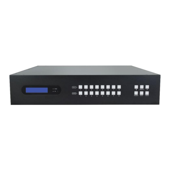
3. Panel Description 3.1 Matrix Switcher Front Panel INPUT MENU/ PRESET BACK DOWN ① LCD Screen: Presents real-time operation status. ② Power LED: Illuminates RED when the device is in standby mode, illuminates GREEN when device is powered on. ③ IR Sensor and its LED: Illuminates RED when the IR sensor receives an IR signal from the IR remote to control the matrix switcher. -
Page 12: Matrix Switcher Rear Panel
3.2 Matrix Switcher Rear Panel RS232 IR EYE TCP/IP ALL IN ALL OUT ① INPUT: Eight type-A female HDMI input ports to connect HDMI sources. ② AUDIO MATRIX OUT/ARC: Eight 3-pin terminal blocks and eight Toslink connectors to connect speakers or amplifiers for HDMI input audio de-embedding or HDBaseT output audio de-embedding, and the eight Toslink connectors can also be used for ARC audio output from HDBaseT receivers. -
Page 13: Receiver Front And Rear Panel
⑦ IR OUT: 1~8: Eight 3.5mm jacks to connect eight IR emitters to send the IR signal received from the corresponding HDBaseT receivers. ALL OUT: 3.5mm jack to connect the IR emitter to send the IR signal received from all HDBaseT receivers. ⑧... - Page 14 HDBaseT link between the switcher/transmitter and the receiver. The HDCP LED illuminates green when the video contains HDCP content. ⑪ DC 24V: DC connector for the power adapter connection. If the switcher/transmitter is connected to the power adaptor, the receiver doesn’t need to connect power adaptor due to the HDBT output port of switcher/transmitter supports 24V PoC output.
-
Page 15: System Connection
4. System Connection 4.1 Usage Precaution Make sure all components and accessories included before installation. System should be installed in a clean environment with proper temperature and humidity. All of the power switches, plugs, sockets, and power cords should be insulated and safe. -
Page 16: Button Control
5. Button Control The matrix switcher can be controlled by using the buttons on the front panel. Whenever a command is accepted, the indicators of all the buttons pressed will blink three times then they will go off. If the command fails, the indicators will go off immediately without blinking. -
Page 17: Panel Button Locking/Unlocking
5.2 Panel Button Locking/Unlocking HDBT Matrix System Locked Press and hold at least three seconds. HDBT Matrix System Unlocked Press and hold to unlock. 5.3 Status Information Inquiry Status Info < EDID Management Press Press enter status information tab. Press navigation buttons to check the previous or next item respectively. -
Page 18: Edid Management
Report the connection status of all HDMI loop output ports. Y means the corresponding output port is connected to a display device, N means there is no connection between the output port and display device. 9~16=HDMI loop output 1~8. 5.4 EDID Management The Extended Display Identification Data (EDID) is used by the source device to match its video resolution with the connected display. - Page 19 Press to confirm. To copy the EDID data from one HDMI output to one or several inputs: Example: Input 1 and 2 learn the EDID data of HDMI output 4. Select Learn HDMI OUT Press to confirm. PRESS INPUT KEY Learn HDMI OUT 1 Press OUTPUT 4 PRESS INPUT KEY...
-
Page 20: Audio Setting
built-in EDID to be invoked Press INPUT 1 and 2. Press to confirm. 5.5 Audio Setting The matrix switcher provides eight analog L+R audio output ports and eight digital SPDIF output ports for audio de-embedding. The audio source selection of these eight audio output ports, and the L+R audio volume can be controlled by the front panel buttons. - Page 21 Example: Select the HDMI input 2 audio source for the analog L+R output 2. Press Press to select AUDIO Setting. Press to enter the tab. Press select L+R OUT 2. Press Press L+R OUT 2 In2 Breakout < to select In2 Breakout Press to confirm.
-
Page 22: Preset Setting
5.6 Preset Setting Press PRESET button can save the current switching routing or load the saved layout preset. Note: The matrix switcher supports nine presets, but only preset 1~4 can be saved and recalled by button control. Please manage other preset by GUI control or RS232 control. -
Page 23: Ip Address Inquiry
5.7 IP Address Inquiry AUDIO Setting IP Address < Press Press to select IP Address Press... -
Page 24: Gui Control
6. GUI Control The switcher can also be controlled via TCP/IP. The default IP settings are: IP Address: 192.168.0.178 Subnet Mask: 255.255.255.0 Type 192.168.0.178 in the internet browser, it will enter the below log-in webpage: Username: admin Password: admin Type the username and password, and then click Login to enter the section for video switching. -
Page 25: Signal Switching
6.1 Signal Switching Use the 8x8 button grid on the page to set which inputs are directed to which outputs. For example, clicking the button on the Input 1 row and Output 1 column, directs input 1 to output 1. Use the 9 numbered buttons under scene area to save and load layout presets. -
Page 26: Audio Setting
6.2 Audio Setting Audio Source Selection • There are sixteen audio sources can be selected for eight analog L+R audio output ports, and twenty-four audio sources can be selected for eight digital SPDIF output ports. - Page 27 L+R Output Audio Volume Control • Adjust L+R output audio volume by the volume bar and the three buttons on the right side.
-
Page 28: Configuration
6.3 Configuration 6.3.1 Down-scaling • Enable/disable video resolution down-scaling function of HDMI output 1~8 ports. When enable down-scaling, the 4K input can be automatically degraded to 1080p output for compatibility with 1080p display which is connected to the HDMI output port. -
Page 29: Hdcp Setting
6.3.2 HDCP Setting • Set the HDCP mode of HDMI and HDBaseT outputs to Passive or Active. Mode Description Automatically follows the HDCP version of source Passive device. If the input video has HDCP content, the HDCP version of HDMI output is HDCP 1.4 for broader Active (Default) video solution. -
Page 30: Edid Copy
6.3.3 EDID Copy • Copy the EDID data from a single output port to one or several input ports. Operation: 1) Select one output port. 2) Select one or several input ports. Press ALL to select all input ports. 3) Click Confirm to save any changes or click Cancel to cancel any changes that have been made. -
Page 31: Edid Setting
6.3.4 EDID Setting Click EDID Setting to enter the below section to set a predefined EDID for input ports. • Select a built-in EDID for one or several input ports. Operation: 1) Select a built-in EDID. 2) Select one or several input ports. Press ALL to select all input ports. 3) Click Confirm to save setting. -
Page 32: Cec Control
6.4 CEC Control If the input source devices, HDBaseT output devices and local HDMI output devices support CEC, they can be controlled via the following CEC interface. 1) Input Source Device Control Select one or several HDMI input source devices to be controlled, and then press function buttons. - Page 33 2) HDBT Output Device Control Select one or several HDBaseT output devices to be controlled, and then press function buttons.
- Page 34 3) HDMI Output Device Control Select one or several HDMI output devices to be controlled, and then press function buttons.
-
Page 35: Rs232 Control
6.5 RS232 Control Send RS232 commands to control third-party devices which are connected to the far-end HDBaseT receivers. Operation: 1) Select the HDBaseT port which is connected to HDBaseT receiver which must have third-party device attached. 2) Set the baud rate. 3) Typing the commands in the box to control the selected remote third-party device which is connected to HDBaseT receiver. -
Page 36: Access Setting
6.6 Access Setting Reset the login admin and user password. Lock or unlock the front panel buttons. Get the GUI and firmware version. Click Confirm to save any changes or click Cancel to cancel any changes that have been made. -
Page 37: Interface Setting
6.7 Interface Setting Modify title bar label, LCD readout and button labels. Click Confirm to save any changes or click Cancel to cancel any changes that have been made. -
Page 38: Network Setting
6.8 Network Setting Static IP or Dynamic Host Configuration Protocol (DHCP). Modify the static IP Address, Subnet Mask, and Gateway. -
Page 39: Gui Upgrade
6.9 GUI Upgrade Please visit at http://192.168.0.178:100 for GUI online upgrade. Type the username and password (the same as the GUI log-in setting, modified password will be available only after rebooting) to login the configuration interface. After that, click Administration in the source menu to get to Upload Firmware as shown below: Select the update file and click Apply button, and then it will start upgrade process. -
Page 40: Ir Control
7. IR Control 7.1 IR Remote Control The matrix switcher has a built-in IR sensor on the front panel for receiving IR control signal from IR remote. In addition, it also provides IR EYE port on the rear panel to connect an external IR receiver for IR local control. -
Page 41: Ir Pass-Through Control
7.2 IR Pass-through Control The matrix switcher supports bi-directional IR pass-through, allowing the devices can be controlled by both source and destination ends. This section provides connection and switching examples to illustrate possible configurations. 7.2.1 Control Local Input Device from Remote The same basic principle applies when controlling the local input device from the remote location. - Page 42 Control local input device through IR ALL OUT port The emitter can be connected to the IR ALL OUT port on matrix switcher to control all local input devices. In this case, the IR receiver must be connected to the IR IN port on each connected HDBaseT receiver, as shown in the diagram below: HDMI: HDBaseT:...
-
Page 43: Control Remote Output Device From Local
7.2.2 Control Remote Output Device from Local The remote displays can be controlled from the local matrix switcher location. Control remote device through IR IN port Example: Switch HDMI input 3 to HDBaseT output 3. Connect an IR receiver to IR IN 3 port on the matrix switcher, then connect an IR emitter to the IR OUT on the receiver, as shown in the diagram below: HDMI: HDBaseT:... - Page 44 Control remote device through IR ALL IN port The receiver can be connected to the IR ALL IN port on matrix switcher to control all remote output devices. In this case, the IR emitter must be connected to the IR OUT port on each connected HDBaseT receiver, as shown in the diagram below: IR Receiver Display Remote...
-
Page 45: Rs232 Control
8. RS232 Control 8.1 RS232 Control Connection 8.1.1 Control the Matrix Switcher from Local To control the matrix switcher from a local PC, the 3-pin to DB9 RS232 Cable is used to connect between the matrix and PC. The connection diagram is shown as below: RS232: RS232 IR EYE... -
Page 46: Control The Matrix Switcher From Remote
8.1.2 Control the Matrix Switcher from Remote To control the matrix switcher from remote location, please connect one or more PCs to the RS232 ports of HDBaseT receivers with the 3-pin to DB9 RS232 Cables. The matrix switcher can be controlled by any one of PCs, the connection diagram is shown as below: HDMI: RS232:... -
Page 47: Control The Remote Third-Party Device From Local
8.1.3 Control the Remote Third-party Device from Local To control a third-party device from local, first determine which HDBaseT receiver is connected to (1 in the diagram below). Next, connect a PC to the corresponding RS232 port of matrix switcher with 3-pin to DB9 RS232 Cable, then connect a third-party device (e.g. -
Page 48: Control The Local Third-Party Device From Remote
8.1.4 Control the Local Third-party Device from Remote To control a third-party device from remote, first determine which HDBaseT receiver is connected to (1 in the diagram below). Next, connect a PC to the RS232 port of HDBaseT receiver with 3-pin to DB9 RS232 Cable, then connect a third-party device (e.g. -
Page 49: Rs232 Control Software
8.2 RS232 Control Software If the matrix switcher and third-party devices needs to be controlled from PC by an RS232 connection, a RS232 control software should be installed in PC. Here using CommWatch.exe as an example. The icon is shown as below: Double-click the icon to run, and its interface is depicted below: Parameter configuration area Monitoring area, show the commands... -
Page 50: Rs232 Commands
Command Description Feedback PowerON. Power on the system. Power ON! PowerOFF. Power off the system. Power OFF! /*Name. Report product name. BG-M88S-H2A-KIT /*Type. Report product model. HDBaseT Matrix V1.0.0 /^Version. Report software version. CPLD:V1.0.0 VideoDriverVersion:V1.0.0 RST. Reset to factory default. - Page 51 Command Example and Command Description Feedback HDMI OUT 02 Down Scale … … HDMI OUT 08 Down Scale DS00OFF. HDMI OUT 01 Down Scale Disable the video resolution down-scaling OFF! DS[XX]OFF. function of HDMI output [XX]. [XX]=00~08. The … … “[XX]=00”...
- Page 52 Command Example and Command Description Feedback MCU OFF! … … RS232 Remote 08 Control MCU OFF! IRRCM00ON. Enable the IR remote-control mode for HDBT IR Remote 01 Control MCU output [XX] that the matrix switcher can be controlled by the IR remote at the far-end IR Remote 02 Control MCU IRRCM[XX]ON.
-
Page 53: Signal Switching
Command Description Feedback Turn ON Output 02! … … Turn ON Output 16! GUI Or RS232 Query Status: HDBaseT Matrix BG-M88S-H2A-KIT V1.0.0 Power ON! HDBT Power ON! STA. Report all system status. Front Panel UnLock! Local RS232 Baudrate Is 9600! GUI_IP:192.168.0.178! - Page 54 Command Example and Command Description Response Output 02 Switch To In 02! Output 03 Switch To In 03! … … Output 08 Switch To In 08! IR01:03. Switch far-end IR IN [YY] to local IR OUT [XX]. [XX]=01~08, [YY]=00~08. The “[YY]=00” IR[XX]:[YY].
-
Page 55: Audio Setting
Command Example and Command Description Response Preset 01 Sta: Out 01 In 01! Out 02 In 01! Out 03 In 01! … … Out 08 In 01! 8.3.3 Audio Setting Command Example and Command Description Response Select audio source [YY] for SPDIF audio output SPDIF01:04. - Page 56 Command Example and Command Description Response AVOLUME01:UM. AVOLUME01:05. AVOLUME01:100. [YY] Description Analog Out 01 Volume 61! Volume Up … … Volume down Analog Out 08 Volume 61! Mute Analog Out 01 Volume Unmute Mute! 00~100 Volume value … … Analog Out 08 Volume Mute! Analog Out 01 Volume UnMute!
-
Page 57: Hdcp Setting
8.3.4 HDCP Setting Command Example and Command Description Response HDCP00MAT. The HDCP content of output [XX] follows the OUT 01 HDCP MAT HDCP version of display device. Display! … … [XX]=00~16. HDCP[XX]MAT. [XX]=00, represents all outputs. OUT 15 HDCP MAT [XX]=01~08, represents HDBT output 1~8. -
Page 58: Edid Management
8.3.5 EDID Management Command Example and Command Description Response All Input EDID Set Default! EDIDMInit. Reset factory default EDID to all input ports. Upgrade the EDID data of the input port [XX]. EDIDUpgrade01. [XX]=00~08, U. EDIDUpgradeU. [XX]=00, represents all inputs. [XX]=01~08, represents HDMI input 1~8. -
Page 59: Third-Party Device Control
Command Example and Command Description Response [XX]=00~08. Input 01 EDID From 01 [XX]=00, represents all inputs. Internal EDID! [XX]=01~08, represents HDMI input 1~8. Input 02 EDID From 01 Internal EDID! … … Input 07 EDID From 01 Internal EDID! Input 08 EDID From 01 Internal EDID! 8.3.6 Third-party Device Control Command... -
Page 60: Cec Control
[X]=6, the baud rate is 57600 1 port. [X]=7, the baud rate is 115200 The “[YY]=00” represents all HDBT outputs. The “[YY]=01~08” represents the HDBT output 1~8. When power off the matrix switcher, CMDOFF/+3/01:123456. automatically send ASCII command “xxx” to power off far-end third-party device. - Page 61 Control the input source: Command Example and Command Description Response CECI02044400 CECI[AA][BB][CC]00. Confirm operation (Enter). CEC Input 02 Send Success! CECI01044401. CECI[AA][BB][CC]01. UP direction. CEC Input 01 Send Success! CECI01044402. CECI[AA][BB][CC]02. DOWN direction. CEC Input 01 Send Success! CECI03044403. CECI[AA][BB][CC]03. LEFT direction.
-
Page 62: Firmware Upgrade
9. Firmware Upgrade Please follow the steps as below to upgrade firmware by the FW port on the rear panel: 1) Prepare the latest two upgrade files and rename them as “08010000.APP” and “08010000.APS” on PC. 2) Power off the switcher, and connect the FW port of switcher to the PC with USB cable. -
Page 63: Panel Drawing
10. Panel Drawing INPUT MENU/ PRESET BACK DOWN 436.6 mm RS232 IR EYE TCP/IP ALL IN ALL OUT Matrix Switcher 140 mm HDBaseT Receiver... -
Page 64: Troubleshooting & Maintenance
11. Troubleshooting & Maintenance Problems Potential Causes Solutions Bad quality of the connecting Try another high-quality cable. cable. Output image with snowflake. Fail or loose connection. Make sure the connection is good. Check with oscilloscope or No signal at the input / output multimeter if there is any signal at the end. -
Page 65: Customer Service
12. Customer Service The return of a product to our Customer Service implies the full agreement of the terms and conditions hereinafter. There terms and conditions may be changed without prior notice. 1) Warranty The limited warranty period of the product is one year. 2) Scope These terms and conditions of Customer Service apply to the customer service provided for the products or any other items sold by authorized distributor only. -
Page 66: Warranty Information (Second Year Assurance)
13. Warranty Information (Second Year Assurance) BZBGEAR wants to assure you peace of mind. We're so confident in the quality of our products that along with the manufacturer's one-year limited warranty, we are offering free second-year warranty coverage upon registration*! Taking advantage of this program is simple, just follow the steps below: 1. -
Page 67: Mission Statement
14. Mission Statement BZBGEAR manifests from the competitive nature of the audiovisual industry to innovate while keeping the customer in mind. AV solutions can cost a pretty penny, and new technology only adds to it. We believe everyone deserves to see, hear, and feel the advancements made in today’s AV world without having to break the bank.
Need help?
Do you have a question about the BG-M88S-H2A-KIT and is the answer not in the manual?
Questions and answers