Advertisement
Quick Links
Assembly Instructions
Item #: L-GZ605PST-A4
IMPORTANT
Thank you very much for choosing Sunjoy Industries.
Please take time to read these instructions thoroughly and follow each step carefully for safe and
easy operation. Keep this manual for future reference.
We would like to hear from you with any comments or suggestions. You can call us toll-free at
1-866-578-6569
anytime 24 hours / 7 days a week. You can also send the email to
customer.care@sunjoygroup.com
or visit
www.sunjoyonline.com
to get tech. assistance or to
place your replacement part order form.
Production Number: 20183572
Advertisement

Related Manuals for Sunjoy L-GZ605PST-A4


Summary of Contents for Sunjoy L-GZ605PST-A4
- Page 1 Assembly Instructions Item #: L-GZ605PST-A4 IMPORTANT Thank you very much for choosing Sunjoy Industries. Please take time to read these instructions thoroughly and follow each step carefully for safe and easy operation. Keep this manual for future reference. We would like to hear from you with any comments or suggestions. You can call us toll-free at 1-866-578-6569 anytime 24 hours / 7 days a week.
- Page 2 Cautions: 1. Keep all children and pets away from assembly area. Children and pets should be supervised when they are in the area of pavilion construction. 2. The area for assembly should not be less than 6 feet from any obstruction such as fence, garage, house, over hanging branches, laundry line or electrical wires.
-
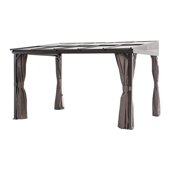
Page 3: Parts List
Parts List Front post 1 Front post 2 Back post 1 Back post 2 Side beam 1 Side beam 2 Decorative slot 1 Decorative slot 2 Junction bar Back beam 1 Back beam 2 Beam junction Middle beam 1 Middle beam 2 Small beam 1 Small beam 2 Small beam... - Page 4 Front card slot 2 Edge beam 1 Edge beam 2 Middle beam PC panel 1 PC panel 2 PC panel 3 PC panel 4 PC panel 5 PC penal card slot Side card slot 1 Side card slot 2 Post base 1 Post base 2 Post base cover 1 Post base cover 2...
-
Page 5: Hardware Pack
Connecting piece 3 Connecting piece 4 Bracket 1 Bracket 2 Bracket 3 Corner support Sidestay1 Sidestay2 Sidestay3 Sidestay4 Curtain Mosquito Net Hardware Pack 1 Bolt M6X20 4PCS Flat washer M6 74PCS Bolt M6X15 38PCS Nut M6 2PCS 76PCS Plastic ring Bolt M6X15 24PCS Bolt M6X35... - Page 6 Fig.1 : Install the curtain-mounting tab (Q) to back post 1 (A3) and back post 2 (A4) with bolt (AA) and flat washer (BB). Ensure the narrow surface of the curtain-mounting tab (Q) faces the post with three holes. Fig.2: Set the post base cover 1 (P1) into the back post 1 (A3)...
- Page 7 Fig.4-1: Insert the junction bar (D) into the decorative slot 1(C1) and decorative slot 2 (C2), and secure with bolt (CC) and flat washer (BB). Fig.5: Install the plastic rings (EE) into the runner of side beam 1 (B1) and side beam 2 (B2), 12 plastic rings for each runner.
- Page 8 Hardware Pack 2 Flat washer M6 56PCS Bolt M6X15 40PCS Nut M6 4PCS Nut M6 12PCS Fig.13, Fig.13-1: Insert the PC panel 3 (M3)(or PC panel 5 (M5)) to the card slot of edge beam and side beam, then insert PC panel 2 (M2)(or PC panel 4(M4)) to the card slot of edge Beam and side beam. Fig.14: Using connecting piece 1 (S1), bolt (CC) and flat washer (BB) to install one side of middle beam (L3) to back beam.
- Page 9 Fig.14-3 : Install another side of middle beam (L3) to decorative slot by using connecting piece 1(S1), bolt (CC) and flat washer (BB). Fig.15: Insert the small beam junction (I) into small beam 1(H1) and small beam 2(H2) and secure them with bolt (CC) and flat washer (BB).
- Page 10 Fig.16: Settle back card slot 1 (J1) and back card slot 2 (J2) to edge beam and middle beam, and secure one side of back card slot to edge beam by using bolt (CC) and flat washer (BB). Fig.16-1: Fix Back card slot 1 (J1) and Back card slot 2 (J2) with Middle beam (L3) by using bolt (CC) and flat washer (BB).
- Page 11 Fig.21-1: Attached Side stay (V1, V2) to Post (A1, A2) with Bolt (CC) and Flat Washer (BB). Fig.21-2: Slid 1pc Plastic Ring (EE) to be inside of Stay 1(V1), then use Bolt (GG) and Washer (BB) to lock top of Side Stay 1(V1), Decorative slot 1(C1) and Side beam 2(B2) together. Repeat this step, lock Side Stay 2 (V2), Decorative slot 2(C2) and Side beam 1(B1) together.
-
Page 12: Care And Maintenance
Care & Maintenance: Our steel components for garden accessories and furniture are treated with rust inhibiting paint that protects it from rusting. However, due to the nature of steel, surface oxidation (rusting) will occur once these protective coatings are scratched. This is not a defect and thus not covered by the warranty.
Need help?
Do you have a question about the L-GZ605PST-A4 and is the answer not in the manual?
Questions and answers