
Related Manuals for Rittal SV9343.070


Summary of Contents for Rittal SV9343.070
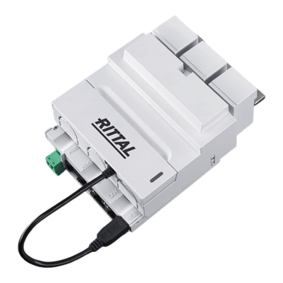
- Page 1 NH measurement module LCD display for monitoring Power pack for display and ModBus SV9343.070 SV9343.170 SV9343.270 SV9343.370 SV9343.400 SV9343.410 Assembly and operating instructions...
-
Page 2: Table Of Contents
ModBus ................. 28 Bus parameters ................28 Data types (DT) ................. 29 5.2.1 Supported data types ..................29 5.2.2 Byte order ...................... 29 Supported ModBus commands............29 5.3.1 Slave address ....................30 5.3.2 Baud rate ....................... 30 Rittal NH measurement module... - Page 3 8.3.1 NH measurement module interfaces .............. 49 8.3.2 Power supply unit for display interfaces ............50 8.3.3 Display for monitoring interfaces ..............50 Measured values................50 Measurement precision (according to EN 61557-12) ......51 Service ................51 Rittal NH measurement module...
-
Page 4: Notes On Documentation
SES (Smart Energy System). CE label Rittal GmbH & Co. KG confirms the conformity of the NH measurement module with the low-voltage regulation 2014/35/EU and with the EMC directive 2014/ 30/EU. A corresponding declaration of conformity has been issued and can be downloaded from the Rittal home page. -
Page 5: Associated Documents
Rittal-branded components or third-party com- solo in combinazione con componenti Rittal o di terze pa l a t ponents approved by Rittal in Mini-PLS, RiLine and Ri4Power systems as de- l l a n i ’... - Page 6 2 Safety instructions Rittal NH measurement module...
-
Page 7: Product Description
3 Product description Product description Functional description The NH measurement module is an accessories product for Rittal NH fuse- switch disconnectors for measuring, acquiring and evaluating electrical perfor- mance data. Tap for current and voltage Forward to the evaluation electronics... -
Page 8: Scope Of Supply
Scope of supply 3.4.1 NH measurement module in the sizes NH00, 1, 2, 3 The SV9343.070, SV9343.170, SV9343.270, SV9343.370 items cover the fol- lowing scope of supply: – NH measurement module in the appropriate sizes NH00, 1, 2 or 3 –... -
Page 9: Serial Number
EN 61000-6-4. Assembly 4.2.1 Connection of the NH measurement module at the NH fuse- switch disconnector with tap-off at the bottom Note: For torque details, refer to the connection terminals of the associat- ed module. Rittal NH measurement module... - Page 10 Use a screwdriver to unlock the protective cover of the NH measurement mod- ule and remove it. Open the safety seating of the NH fuse-switch disconnector and remove it. Use a screwdriver to unlock the contact hazard protection cover and then re- move it. Rittal NH measurement module...
- Page 11 Push the NH measurement module with the connection conductors into the frame terminals of the NH fuse-switch disconnector and fasten it with the pre- scribed tool and torque. Snap-in the contact hazard protection cover of the NH fuse-switch disconnec- tor. Rittal NH measurement module...
- Page 12 After connecting the tap-off cable, snap the protective cover of the NH meas- urement module on again. Insert the mini-USB connector in the socket at the lower right on the NH meas- urement module. Rittal NH measurement module...
-
Page 13: Assembly With The Tap-Off At The Top (Only Size Nh00)
1.5 mm² cable. Note: Appropriate conductor protective terminals are described in the "RiLine accessories" area of the current Rittal manual. 4.2.2 Assembly with the tap-off at the top (only size NH00) The NH measurement module of size NH00 can also be assembled with the tap- off at the top on the NH fuse-switch disconnector. -
Page 14: Control And Display Components
The power can be supplied via the CAN bus. 24 VDC is present at pins 3 and 6, GND is present at pins 4 and 5. Whereby, it suffices to assign pins 3 and 4. The Rittal NH measurement module... -
Page 15: Led Displays
Data is displaced Orange Orange flash- processing ing (1/s) Not connected, file er- Configuration: defec- Both LEDs flash orange for 10 tive file, incorrect pa- seconds. rameters Tab. 5: Status messages for faults in the USB communication Rittal NH measurement module... -
Page 16: Energising
4 kV. The de-energisation de- scribed in the following steps permits a maximum loading of 6 kV. Remove the cover. Pull the lower part of the NH measurement module with the communications connections downwards. clic! Rittal NH measurement module... - Page 17 Ensure that the other end of the USB adaptor present in the cover is connect- ed to the NH measurement module. The electronics are now de-energised and the NH measurement module can be loaded with maximum 6 kV. Proceed in the reverse order to reconnect the measurement electronics. clic! Rittal NH measurement module...
-
Page 18: Configuration Files
A line break must follow the last parameter to be interpreted; this means that the last line is empty. 4.4.2 File structure Note: The time of day for the USB logging can be set via ModBus or the display available as accessory. Rittal NH measurement module... -
Page 19: Serial Number
// AL: alarm low, AH: alarm high // WL: warning low, WH: warning high // HY: hysteresis // U: phase-phase voltage // VN: phase-neutral voltage+ // I(N): current (neutral) // P/Q/S: active/reactive/apparent power UAL;0 UAH;45000 UWL;0 Rittal NH measurement module... - Page 20 3 · U · I Power warning LOW -3 · U · I 3 · U · I Power warning HIGH -3 · U · I 3 · U · I Power hysteresis Tab. 6: "Alarm configuration" parameter Rittal NH measurement module...
-
Page 21: Logging.cnf
Phase-neutral V3N effective voltage UMAX U12, U23, U31 maximum voltage UMIN U12, U23, U31 minimum voltage UAVG U12, U23, U31 average voltage VMAX V1N, V2N, V3N maximum voltage VMIN V1N, V2N, V3N minimum voltage Tab. 7: Logging configuration parameters Rittal NH measurement module... - Page 22 Phase 2 PF2 power factor Phase 3 PF3 power factor Total power factor FREQ F mains frequency THDFU12 THDf of U12 THDFU23 THDf of U23 THDFU31 THDf of U31 THDFI1 THDf of I1 Tab. 7: Logging configuration parameters Rittal NH measurement module...
-
Page 23: System.cnf
Tab. 8: System configuration parameters // System configuration // Serial number (max. 10 characters) SERIAL;1501700000 // ModBus address: 1…247 MODADR;247 // ModBus baud rate: 9600 / 19200 / // 38400, 8E1 MODBAU;19200 // Topology: // 1/2: 3-/4-wire bottom mounting Rittal NH measurement module... -
Page 24: Access Via Usb
USB cable to a PC. Fig. 4: Front cover of the NH measurement module 4.5.2 Access via computer To connect the NH measurement module to a computer, you require a commer- cially available micro USB cable. Rittal NH measurement module... -
Page 25: Access Via Usb Stick
USB stick connection to the NH measurement module Firmware update 4.6.1 General information Note: When the NH measurement module is operated with a CMC III PU, the firmware is updated automatically via the CMC III PU. Rittal NH measurement module... -
Page 26: Firmware Update Via A Personal Computer
USB"), whereby a firmware file (.img) is required. This file can be downloaded from the Rittal home page. The actual update is made via the computer (see section 4.6.2 "Firmware update via a personal computer") or via a USB stick (see section 4.6.3 "Firmware update via a USB stick"). -
Page 27: Operating Via The Cmc Iii Processing Unit Home Page
On the Settings tab, similar to the CMC III PU, the access rights for the NH measurement module (Settings for unit access rights button) as well as the alarm notification are specified individually (Settings for all alarms button). Rittal NH measurement module... -
Page 28: Modbus
ModBus Terms and definitions Term Description NULL Termination of an ASCII string with "\0" NH measurement Rittal NH measurement module module Tab. 9: Terms and definitions Abbreviations Abbreviation Description Access rights (read/write) Data type Resolution, number of fractional digits contained within a pa- rameter, i.e. -
Page 29: Data Types (Dt)
The supported ModBus commands are summarised in 15. Command Description 0x03 Read Holding Registers (see sections 5.4 and 5.5) 0x06 Write Single Register (see section 5.4) 0x10 Write Multiple Register (see section 5.4) Tab. 15: ModBus commands Rittal NH measurement module... -
Page 30: Slave Address
5.3.3 Time synchronisation Setting the device's time can also be achieved by writing the register 0xD005 of the device settings. The command described below is sent as broadcast frame. Rittal NH measurement module... -
Page 31: Device Settings
3 = 3-wire system, top mounting 4 = 4-wire system, top mounting 0xD005 Set UTC date and time: 2147483647 Seconds from 1 January 2000, 00:00 0xD007 UTC date and time: Add-on in ms Tab. 18: Device settings Rittal NH measurement module... - Page 32 0xD028 Current: Warning threshold low 0xD02A Current: Warning threshold high 0xD02C Current: Hysteresis 1000 0xD02E Current neutral: Alarm threshold low 0xD030 Current neutral: Alarm threshold high 0xD032 Current neutral: Warning threshold low Tab. 18: Device settings Rittal NH measurement module...
- Page 33 = 720 A => P = 324 kW Min = -P / RES = -32400 Max = P / RES = 32400 => Qtot = 3 · Q = 972 kW Min = -Qtot / RES = -97200 Rittal NH measurement module...
-
Page 34: Data Register
Maximum voltage U12, U23, U31 45000 0x0030 Maximum voltage V1N, V2N, V3N 26000 0x0032 Maximum current I1, I2, I3 0x0034 Maximum active power P1, P2, P3 0x0036 Maximum reactive power Q1, Q2, Q3 kvar Tab. 19: Data register Rittal NH measurement module... - Page 35 Direct active energy EaIN 2147483647 0x0074 Reverse active energy EaOUT 2147483647 0x0076 Absolute active energy Ea custom 2147483647 0x0078 Absolute active energy runtime 2147483647 0x007A Absolute active energy custom runtime 2147483647 0x007C Temperature 2147483647 °C Tab. 19: Data register Rittal NH measurement module...
- Page 36 7: Alarm, value too low 8: Alarm, value too high 9: Warning, value too low 6) The temperature state uses the same values as in 5), but only supports the states: 4: Value OK 8: Alarm, value too high Rittal NH measurement module...
-
Page 37: Alarm Configuration
(see limits and additional notes in table 19). There is no separate activation/deactivation configuration for the alarms/warn- ings available. To use alarm and warning functionality without the hysteresis, the corresponding values are simply configured to 0%. Rittal NH measurement module... -
Page 38: Device Identification
A user block request starts with a command request header, which is described in the table below: Byte Data Description 0x43 Command “User Block” 0x16 Magic number (MSB) 0x64 Magic number (LSB) Tab. 22: Command request header Rittal NH measurement module... -
Page 39: Example
The example shows a setup of user block with ID 1 and with 4 variables (3 data registers and 1 device settings register). Command request header 0x43 0x16 0x64 0x01 0x01 0x04 0xD004 0x0002 0x0100 0x0200 The response only contains the header. Rittal NH measurement module... - Page 40 Therefore, only a write access with a maximum number of 1 variable is al- lowed in this case. Command request header 0x43 0x16 0x64 0x03 0x01 0x01 0xD004 The response only contains the header. Response header 0x43 0x03 0x01 0x01 Rittal NH measurement module...
-
Page 41: Accessories For Installation And Operation
The accompanying cable is 2 metres long. Try to place the power supply unit and display so that the cable length suffices for connect- ing the devices. Longer cables are commercially available. An RJ 11 cable may also be used. Rittal NH measurement module... -
Page 42: Operation Of The Lcd Display For Monitoring
Navigate with the "→" (F1) or "←" (F4) arrow key to the "Extra" menu item on the "Setup Selection" display and press "OK" (F3) to confirm the "Device List" menu item. Select with the "↓" (F2) arrow key a free line (000 -------). Rittal NH measurement module... - Page 43 Enter your specified ModBus address in accordance with the same operating scheme as in the previous step. Confirm your input by pressing the "save" (F3) key and wait approx. 5 seconds. The display does not accept any inputs during this time. Rittal NH measurement module...
- Page 44 Press the "ok" (F4) key on the "Edit device name" screen to confirm the cur- rently selected alphabetic character of the upper row. Press the "→" (F2) and "↓" (F3) keys to change the currently selected alphabetic character. Press the "↰" (F1) key to confirm the entered name. Rittal NH measurement module...
-
Page 45: Adaptation Of The Measurement Module Topology
To exit the menu without changing the baud rate, press "↰" (F1). 6.3.4 Setting the language of the LCD display for monitoring Navigate with the "→" (F1) or "←" (F4) arrow key to the "Extra" menu item on the "Setup selection" display. Rittal NH measurement module... -
Page 46: Setting The Display Illumination
Storage and disposal Storage If the device are not used for a long period, Rittal recommends that you discon- nect it from the mains power supply and protected from damp and dust. Disposal Since all the described products consist mainly of the "housing" and "circuit board"... -
Page 47: Technical Specifications
Power supply unit for display and ModBus ambient conditions Ambient conditions Ambient temperature -5°C…+55°C Storage and transport tempera- -25°C…+85°C ture Humidity 5%...95% relative humidity, non-condensing Tab. 29: Power supply unit for display and ModBus ambient conditions Rittal NH measurement module... -
Page 48: Display For Monitoring Ambient Conditions
CAT III / 300 VAC (DIN EN 61010-1) CAT III corresponds to the distribution level External power supply 24 VDC (-10% / +20%) Connection RJ 45 Rittal CAN, looped-through Controller and communication optional supply, RTC buffering Instrumentation voltage inputs Phase count Phase - N voltage 230 VAC (±10%) -
Page 49: Power Supply Unit For Display Electrical Specifications
Output voltage 24 VDC Tab. 32: Power supply unit for display electrical specifications Interfaces 8.3.1 NH measurement module interfaces Interfaces CAN bus Rittal-specific as Looped-through CMC III sensor Baud rate 100…1000 kbit/s (depending on the cable length) Common mode rejection -27…+40 V... -
Page 50: Power Supply Unit For Display Interfaces
S with regard to a 15-minute interval. cos φ Calculation of the power factor. THD U/THD I harmonics Calculation of the harmonics to 31st order; val- ues on request. Frequency of refreshing the Every 1 second measurement Tab. 36: Measured values Rittal NH measurement module... -
Page 51: Measurement Precision (According To En 61557-12)
Power measurement with con- Class 2 verter Tab. 37: Measurement precision Service For technical queries, please contact: Tel.: +49(0)2772 505-9052 E-mail: info@rittal.de Homepage: www.rittal.com For complaints or service requests, please contact: Tel.: +49(0)2772 505-1855 E-mail: service@rittal.de Rittal NH measurement module... - Page 52 ◾ Enclosures ◾ Power Distribution ◾ Climate Control ◾ IT Infrastructure ◾ Software & Services You can find the contact details of all Rittal companies throughout the world here. www.rittal.com/contact...
Need help?
Do you have a question about the SV9343.070 and is the answer not in the manual?
Questions and answers