
Related Manuals for Cembre RHU 1000


Summary of Contents for Cembre RHU 1000
- Page 1 SINGLE & DOUBLE ACTING HYDRAULIC PRESSHEAD RHU1000 ENGLISH OPERATION AND MAINTENANCE MANUAL...
-
Page 2: Warning Labels
WARNING LABELS TG. 0934 WARNING DANGER CAUTION TG. 0947 Operation and safety methods BEFORE USING THIS TOOL READ THE SAFETY may vary in accordance with WARNINGS and recommended practices described in ELECTROCUTION the guidelines of each utility. HAZARD the manual. Failure by the operator to read and fully For your own safety, ensure 40 mm understand the warnings will leave this person unquali-... -
Page 3: Safety Nut
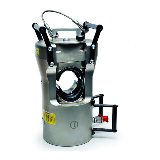
Description: HOLDER HANDLE DIE RETAINING PIN VENT PLUG (for single acting) DIE RELEASE PIN MALE QUICK RELEASE COUPLER LIFTING EYE (for suspended use) LIFTING HANDLE SAFETY NUT DIE HOLDER LATCH 200 TOP DIE HOLDER COUPLER PROTECTION HANDLE 202 RAM... -
Page 4: General Safety
GENERAL SAFETY – Use this tool for its intended purpose only. – Inspect tool before use, replace any worn or damaged parts. – Inspect pump hydraulic hoses and couplings before each use. – Clear work area. – Operating & Safety procedures may vary in accordance with the working guide lines established by each utility or contractor. - Page 5 Always use RHU1000 on a level and stable surface, e.g the ground. Alternatively, the head may be suspended for use via the lifting eye (47) (refer to § 2.7). The head is equipped with a “self-lock” quick male coupler and can be connected to Cembre single acting hydraulic pumps developing 700 bar (10,000 psi) pressure.
- Page 6 2.3) Ram advancing and die positioning – Locate the connector between the dies at the crimp position, if nesessary open the head following instructions as per § 2.6. – Operate the pump until the dies touch the connector. upper die Make sure that dies are exactly positioned on desired crimp point, otherwise re-open dies conductor...
- Page 7 2.6) Head opening When required, the upper part of the head can be removed to permit an easy introduction of the connector or removal of it after crimping. Fig. a Proceed as follows (with reference to Fig. a): Hold the handle (1) and pull the latch (9). Turn the top die holder (200) through 90 degrees.
- Page 8 2.7) Lifting eye installation To use the head in suspension mode for aerial operations, it is necessary to use the lifting eye: – Remove lifting eye from case lid. – Screw locking nut fully onto lifting eye. – Turn the head upside down and screw locking lifting eye completely into its seat, then tighten locking nut against the head.
-
Page 9: Maintenance
All maintenance or disassembly should take place on a flat, clean work surface covered if necessary so as to have a clean space for the disassembled parts. Inspect each part during disassembly for wear, scratches, cuts and always replace with new Cembre original parts. Worn or damaged parts may malfunction during head operation. -
Page 10: Conversion Instructions
4. CONVERSION INSTRUCTIONS Before starting conversion always check that the ram is completely retracted and the pump hose is disconnect from the head. UPPER PLUG VENT - FROM SINGLE TO DOUBLE ACTING - – Remove upper plug vent from the head, insert female coupler Q38-F and nipple 3/8”... -
Page 11: Safety Precautions
NOTICE: This tool has undergone a magnetic particle inspection (MAGNAFLUX test) and is certified in accordance with ASTM-E1444, MIL-STD-271F, MIL-STD-1907. SAFETY PRECAUTIONS: A Non-Destructive Testing (NDT) should be performed by a suitably qualified body after the first two years of service, then annually, and the evidence of the execution marked on the tool, local to its serial number with the date shown as MMYY. - Page 12 10-3 ▲...
- Page 13 Torque setting Lbf ft ▲ 14.8 ▲ Tool serial number TABLE 1...
- Page 14 Code N° DESCRIPTION TABLE 1 FORK 6232683 TG.0926 TOOL NAMEPLATE The items marked "K" are those 6900426 M8x30 SCREW Cembre recommend replacing 6100043 if the tool is disassembled. 6003936 SCRAPER 6362099 SEAL When ordering spare parts always 6002248 PLUG VENT...
-
Page 15: Dimensions Mm (Inches)
Centre; if possible, include a copy of the Test Certificate supplied by Cembre with the tool or, if no other references are available, indicate the approximate purchase date and the tool serial number. - Page 16 CS 92014 - 91423 Morangis Cédex E-mail: sales@cembre.com E-mail: sales@cembre.co.uk E-mail: info@cembre.fr www.cembre.com www.cembre.co.uk www.cembre.fr Cembre España S.L.U. Cembre GmbH IKUMA GmbH & Co. KG Cembre Inc. Calle Verano 6 y 8 Heidemannstraße 166 Boschstraße 7 Raritan Center Business Park 28850 Torrejón de Ardoz...
Need help?
Do you have a question about the RHU 1000 and is the answer not in the manual?
Questions and answers