
Subscribe to Our Youtube Channel
Related Manuals for Cembre LD-2EN


Summary of Contents for Cembre LD-2EN
- Page 1 15 M 073 E ENGLISH Certified Quality Certified Environmental Certified Occupational Management System Management System Health & Safety Management System LD-2E RAIL DRILL TYPE LD-2E-110 LD-4EF OPERATION AND MAINTENANCE MANUAL...
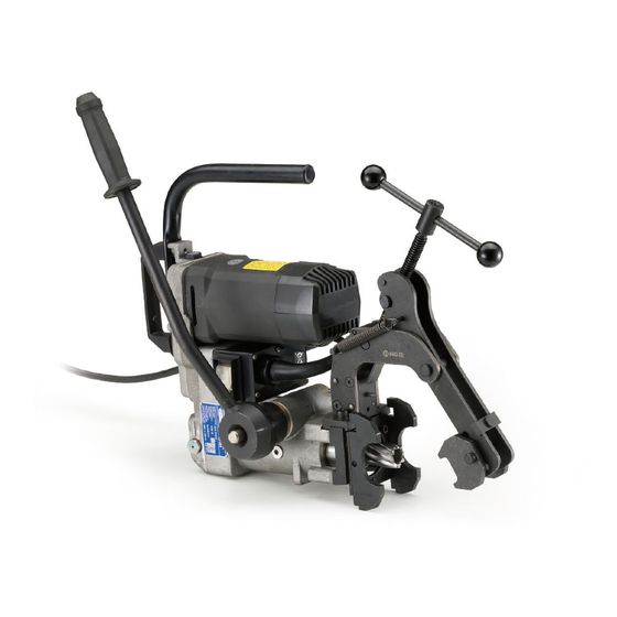
- Page 2 DESCRIPTION OF THE DRILLS: LD-2EN LD-2EN-110 LD-4EN basic drills LD-2E LD-2E-110 LD-4EF basic drills complete with DBG-F2 railweb clamping device...
-
Page 3: User Information
ATTENTION – Before using the rail drilling, carefully read the instructions contained in this manual. SAVE THESE INSTRUCTIONS: this manual contains important safety and operating instructions for the drilling machine. – The degree of protection of the drilling machine against moisture is classified “ordinary"... -
Page 4: General Characteristics
1. GENERAL CHARACTERISTICS LD-2E LD-2E-110 LD-4EF Ø 7 ÷ 33 mm Ø 7 ÷ 40 mm Ø 7 ÷ 33 mm Drilling capacity (*): 310 rpm 250 - 280 rpm (**) 310 rpm Speed without load: Single phase, double insulation Electric motor: 110 / 120 V AC-DC 220 / 230 V -50 Hz... - Page 5 2. ACCESSORIES SUPPLIED WITH THE DRILL 2.1) Guide bits for controlling the coolant system: for broach cutters suitable for drilling thicknesses of up to 25 mm – 1 pc PP 1, diameter 7 mm. – 1 pc PP 2, diameter 8 mm. for broach cutters suitable for drilling thicknesses of up to 50 mm –...
-
Page 6: Accessories To Be Ordered Separately
3. ACCESSORIES TO BE ORDERED SEPARATELY 3.1) DBG-F2 device (*) with moving arm for clamping the drill to the rail web and track fittings, complete with the following end pieces: – TDB 1: for switch blades and compound frogs. – TDB 3: for repairing (adjusting) existing holes on rails for subse- quent application of electrical connections and for additional special applications. - Page 7 – MPAF UIC54 on DRILLING AXIS of UIC 54 rail – MPAF UIC60 on DRILLING AXIS of UIC 60 rail • Note: Contact Cembre for selection of specific application accessories. 3.5) MPAU universal positioning template suitable both for repair- ing existing holes on various fittings, and for drilling disused rails.
- Page 8 CY320L CY330 CY330L MAX DRILLING THICKNESS MAX DRILLING THICKNESS 25 mm 50 mm Contact Cembre for other types of broach cutters. Broach cutters resharpening must be carried out in compliance with appropriate modes of operation which allow the best result.
- Page 9 3.10) Spiral bits APED... FIG. 1 APE... L max L max FIG. 2 SPECIAL SPIRAL BITS FOR RAILS IN STEEL QUALITY 700 - 900 - 1100 (UIC 860.0) Spiral Bit Spiral Bit Adaptor Adaptor Ø Ø type type type type PE 70 PE 140 APED 70...
- Page 10 (02). The use of the lubrocoolant supplied by Cembre, in the recommended concentrations, guarantees optimum use of the drilling tools.
- Page 11 • The drill is equipped with a coolant attachment valve (35) and a vent valve (17) which are located as shown (Fig. 3). If under certain operating circumstances they need to be interchanged, proceed as follows: – Using a 17 mm hexagonal spanner unscrew the vent valve from its seat. –...
- Page 12 5. SPINDLE ADVANCE LEVER (Ref. to Fig. 6) The spindle is advanced by moving the lever (36) (see Fig. 6a). The lever is fitted with a release pawl (39) which, when pressed, renders it inde- pendent of the hub and hence the spindle; the operator can therefore easily vary the angular position of the lever without movement of the spindle (Fig.
- Page 13 6. PREPARING THE RAIL DRILL DISCONNECT always the power supply when servicing the drill: before removing the broach cutters, spiral bits, positioning templates etc. 6.1) Assembling broach cutters (Ref. to Figs. 8-11). 6.1.1) Insert the guide bit in the cutter from the side of the spigot. 6.1.2) Using the lever (36), position the spindle shaft (07) so that both grub screws (18) become accessible and sufficient space is provided to insert the cutter;...
- Page 14 6.2.2) Insert into the spindle shaft, the DPE spacer required to activate the coolant system. If it is necessary to use an APE... adaptor the bit must first be fitted in the corresponding APE adaptor and locked with the appropriate grub screw, then the DPE spacer inserted. Note: Adaptors type APED…...
- Page 15 7. RAIL DRILL TYPE LD-2E ; LD-2E-110 ; LD-4EF Code n. LD-2E ; LD-2E-110 ; LD-4EF each cover a basic drill (see page 1) complete with the moving arm device DBG-F2 for clamping to the rail web and the track fittings (Ref. to Fig. 12). The DBG-F2 clamping device consists of: –...
- Page 16 7.1) Assembling end pieces TDB 1, TDB 6 and TDB 3 end pieces of the DBG-F2 device, with moving arm, have been designed for adaptation to the different operating conditions on rails and track fittings; their assembly is shown in Fig. 13. •...
- Page 17 7.3) Assembly positioning templates (Ref. to Fig. 15) NOTE: Only Cembre positioning templates and jigs are to be used with the rail drill. 7.3.1) The type MPAF.. and MPAU positioning templates are secured to the front plate (04) of the drill by means of the two socket head cap screws M 6x16 supplied.
- Page 18 7.4) Clamping to the rail web (Ref. to Fig. 16) The drill has a rapid rail engagement/release mechanism and specially shaped positioning templates for each rail type which facilitate precise and certain location of the part to be drilled. To fully exploit the special features of the engagement device, we recommend calibrating it to the rail type to be drilled as follows: 7.4.1) Withdraw the spindle shaft (07) completely by means of the lever (36).
-
Page 19: Automatic Switch
8. DRILLING (Ref. to Figs. 17-18) N.B.: make sure the mains voltage corresponds to that on the drill rating plate. N.B.: switch on the cooling system before starting the drill (§ 4). 8.1) Drill fitted with “short” type broach cutter (for drilling thicknesses of up to 25 mm). The drilling sequence may be started with the drill fitted with the broach cutter (§... - Page 20 8.1.5) ONLY FOR LD-4EF DRILL ONLY FOR LD-4EF DRILL: switch for changing of the spindle speed Set the motor speed, by means of the selector switch under the automatic switch (see Fig. 17e), in correlation to the diameter of the hole to be.
- Page 21 Approach Start drilling with discharge of lubrocoolant Drilling Finish drilling with removal of swarf and switching off of lubrocoolant The slug is ejected upon completion of the drilling operation FIG. 19 – COOLANT DRILLING WITH BROACH CUTTER 8.3) Drill fitted with special spiral bit Follow the sequence described in §...
- Page 22 9. SPA... POSITIONING PLATE 9.1) Instruction for drilling close to rail heads FIG. 21 9.1.1) Fit the MPAF... positioning template corresponding to the rail to be drilled(see § 7.3). 9.1.2) Insert the SPA... positioning plate (03) relating to the rail to be drilled in the appropriate housing (see Fig.
- Page 23 9.2) Drilling in line with rail heads (Ref. to Fig. 23) 9.2.1) Fit the MPAF... positioning template corresponding to the rail to be drilled (see § 7.3). 9.2.2) Fit the MRF clamp on the head of the rail, keeping it in contact with the rail head at the reference point of the drilling centres.
- Page 24 For clarity the drill is not shown in the figures Reference point of distances Reference point of distances FIG. 24 – POSITIONING...
-
Page 25: Storing The Drill
10.4) Place the drill and the SR5000 coolant unit in a sealed place free from dust, moisture and the risk of accidental impact. For better protection Cembre recommends the use of the VAL LD metal case designed for this purpose (see § 3.4), which enables the drill to be inserted thanks to the DBG-F2 clamping device, and to be locked in the case. -
Page 26: Maintenance
11. MAINTENANCE Before servicing or maintenance, stop the motor and disconnect the plug from the electric source. After first 10 operating hours, proceed with sump oil change, as follows: (Ref. to Fig. 26a and 26b) – Remove the cap with the magnetic insert (21). –... -
Page 27: Coolant Filter Cleaning
11.1.2) Removal of metallic residues from the crankcase When the drill is positioned as shown in Figure unscrew the appropriate cap, with magnetic insert (21) on which any metallic residue will have collected. Carefully clean the magnetic insert with a clean rag and screw it back in the appropriate housing. - Page 28 11.3) SPECIAL MAINTENANCE OF THE DRILL The special maintenance operations require the intervention of qualified personnel only, Please contact Cembre (See § 13). APPENDIX “A” Factors which influence the number of holes that can be made according to the tool used.
- Page 29 ..............................96,6 dB (A) Protection of operators against risksof exposure to noise during work. Cembre drills type LD-2E and LD-2E-110 are designed and constructed according to EEC directives 80/1107 and 86/188 relating to the protection of operators against risks arising from exposure to chemical, physical and biological agents during work, and with particular regard to the risk of exposure to noise.
- Page 30 300 holes/day, the daily exposure to noise would be 82.2 dB(A). Since noise levels vary according to the many different operating conditions, Cembre engineers are available to give further details on the correct use of the drills.
-
Page 31: Return To Cembre For Overhaul
Centre; if possible, attach a copy of the Test Certificate supplied by Cembre together with the drill or, if no other references are available, indicate the approximate purchase date and the drill... - Page 32 Guarantee conditions cease upon usage of non original spare parts. When ordering spare parts always give the following information: - spare part code - spare part description - drilling machine model - drilling machine serial number FIG. 29 – DRILL ASSEMBLY...
- Page 33 Electric plug Electric motor 6001209 Magnetic cap 6001422 Brush 6900060 Screw M 4x8 6380316 Handle 6380330 Handgrip 6001731 Guard 6001198 Lubricator 6001210 6001397 Complete air valve 6001238 Carrying handle 6001144 Front plate 6001262 Spindle advance lever 6001146 Drilling spindle 6360480 O-ring 6340160 M 8x10 grub screw...
- Page 35 9. SPA... Positioning plate ..........................21 10. Storing the drill ............................24 11. Maintenance ............................... 25 12. Warnings ..............................30 13. Return to Cembre for overhaul ..................... 30 Appendix “A” ................................. 27 Appendix “B” ................................. 28 Appendix “C” ................................ 29...
- Page 36 CS 92014 - 91423 Morangis Cédex E-mail: sales@cembre.com E-mail: sales@cembre.co.uk E-mail: info@cembre.fr www.cembre.com www.cembre.co.uk www.cembre.fr Cembre España S.L.U. Cembre GmbH Cembre Inc. Calle Verano 6 y 8 Heidemannstraße 166 Raritan Center Business Park 28850 Torrejón de Ardoz - Madrid (España) 80939 München (Deutschland)
Need help?
Do you have a question about the LD-2EN and is the answer not in the manual?
Questions and answers