Advertisement
PARTS REQUIRED –
PZQ60-00341 :
Description
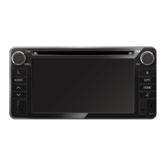
Head Unit
Bolts (M5x8)
Cable ties
GPS Antenna
GPS Antenna earth plate
Owner's Manual
PZQ60-00350 :
Description
Patch Harness
PZQ60-00230 :
Description
Patch Harness
C-HR │ Dec '16 Onwards
C-HR SATELLITE NAVIGATION
SATELLITE NAVIGATION KIT
Part No.
PZQ60-00345
-
-
PZQ60-00260
-
PZQ60-00346
PATCH HARNESS
Part No.
PZQ60-00350
PATCH HARNESS
Part No.
PZQ60-00230
QTY
1
8
14
1
1
1
QTY
1
QTY
1
Issue: 2.0 │ Date: July 2018 │ Page 1 of 10
Advertisement
Table of Contents

Related Manuals for Toyota PZQ60-00341


Summary of Contents for Toyota PZQ60-00341
- Page 1 PARTS REQUIRED – C-HR SATELLITE NAVIGATION PZQ60-00341 : SATELLITE NAVIGATION KIT Description Part No. Head Unit PZQ60-00345 Bolts (M5x8) Cable ties GPS Antenna PZQ60-00260 GPS Antenna earth plate Owner’s Manual PZQ60-00346 PZQ60-00350 : PATCH HARNESS Description Part No. Patch Harness...
- Page 2 1. PARTS REMOVAL – C-HR SATELLITE NAVIGATION Step 1. Remove the Audio Facia Panel. Remove negative terminal of battery before proceeding with installation. When removing panels, take note of the location of clips as shown in diagrams. Unless otherwise instructed, have all temporarily removed parts stored in a safe location where no damage can occur.
- Page 3 2. GPS ANTENNA INSTALLATION – C-HR SATELLITE NAVIGATION Step 1. Peel the earth plate sticker, before installing the GPS antenna on to the earth plate. Prior to installing the GPS Antenna Earth Plate, ensure that the surface of the Earth Plate has been cleaned using an alcohol based cleaner.
- Page 4 3. HEAD UNIT INSTALLATION – C-HR SATELLITE NAVIGATION Step 1. Attach brackets to Head Unit as shown, using the M5x8 Bolts provided. DO NOT USE SELF-TAPPING SCREWS! Using self-tapping screws on the Head Unit will damage internal parts of the unit and will render the Head Unit inoperable or un- repairable.
- Page 5 3. HEAD UNIT INSTALLATION – C-HR SATELLITE NAVIGATION Step 3. Connect the connectors to the Head Unit as shown in the diagram below. Head Unit Connection Schematic Diagram Vehicle Harness: Description Connector Main connector 10 pin male Rear speakers connector 6 pin male Steering switch, speed and reverse signal connector 28 pin male...
- Page 6 4. RE-INSTALLATION – C-HR SATELLITE NAVIGATION Step 1. Re-install all temporary removed parts. Ensure that all panels are correctly aligned and that no gaps are present. Step 2. Reconnect the battery. Note: When re-fitting battery post terminal clamp, torque to be between 2.9 – 7.8 Nm. Step 3.
- Page 7 5. SYSTEM CHECK – C-HR SATELLITE NAVIGATION Step 1. Turn the key to IG ON, and perform the following system checks. Rear Camera Display Check : Shift the gear to REVERSE and check the audio display screen. • If the audio screen shows the rear view: OK •...
- Page 8 5. SYSTEM CHECK – C-HR SATELLITE NAVIGATION If the audio screen shows “Microphone not connected” Check the connection of connectors 6 of the Head Unit Schematic Diagram and repeat the checks. Step 3. Drive the vehicle for a few hundred meters to an outdoors area, where there will be no interference to the GPS signal (i.e.
- Page 9 5. SYSTEM CHECK – C-HR SATELLITE NAVIGATION Step 4. System Sensors Check Press “Function Check / Setting”. Step 5. Press “System Sensors Check”. Step 6. Check that; • GPS Status is “OK (3D)”. If not, check the installation of the GPS Antenna, including the connection of connector 9 of the Head Unit Schematic Diagram.
- Page 10 5. SYSTEM CHECK – C-HR SATELLITE NAVIGATION Step 7. After all system checks have been checked and rectified, press and hold POWER button until the Head Unit restarts. Step 8. End of Head Unit installation. C-HR │ Dec ‘16 Onwards Issue: 2.0 │...
Need help?
Do you have a question about the PZQ60-00341 and is the answer not in the manual?
Questions and answers
I have same audio setup but sounds not working i got recently to fixed my Toyota Prius. Is this setup doesn’t have amplifier