Table of Contents
Advertisement
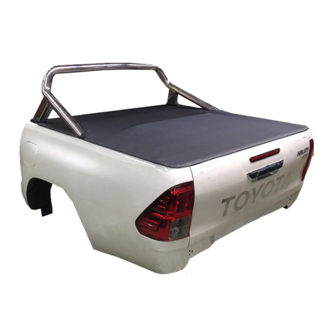
HARD TONNEAU COVER FITTING INSTRUCTIONS
Accessory Part No. PZQ70-89870
Place these instructions in vehicle's glove box after installation is complete
General Notes
-
Read through the fitting instructions before installation of accessory.
-
Always install the accessory following the fitting instructions. Failure to do so may cause damage to the vehicle or
the accessory.
-
Ensure all recyclable discarded vehicle accessory components and packaging are recycled following local
recycling regulations.
-
It is always recommended that this accessory is fitted by a qualified Toyota Technician.
-
Safely store and protect any removed vehicle components.
-
Ensure all bare metal surfaces are protected using Automotive Bare Metal Primer and touch-up paint.
-
Remove all metal swarf and dust from all vehicle surfaces if surface is used for accessory installation.
Safety Notes
- Check that all work practices comply with safety standards.
- Please wear appropriate clothing and use safety equipment.
Care Instructions:
Please check content of kit using this list and subsequent sketches. Advise discrepancies to TMCA at once.
IMPORTANT!
MAINTENANCE
ISSUE 4: 09/10/18
PARTS, SERVICE & ACCESSORIES
HILUX 'A' DECK
(With Sports Bar)
September, 2016 Production Onwards
Clean Tonneau Cover
with a mild detergent and
water solution.
Do not stand/sit or rest heavy objects on Tonneau Cover.
Humans or animals are not to be under the closed Tonneau Cover at any time.
Securely lock Tonneau Cover before operating vehicle.
Tonneau Cover is not dust or water tight.
Do not carry open volatile chemicals with Tonneau Cover installed.
If contact with volatile chemicals occurs clean Tonneau Cover with mild detergent and water solution.
If lubrication of the locks or hinges is required use only Graphite Powder.
DO NOT use any other lubricants or oils.
Accessory Part No. PZQ70-89870
Installation Time: Approx. 4h 15min
Do not use abrasive
cleaners or solvents.
TC0403c
Page 1 of 34
Advertisement
Table of Contents

Related Manuals for Toyota HILUX ‘A’ DECK


Summary of Contents for Toyota HILUX ‘A’ DECK
- Page 1 Ensure all recyclable discarded vehicle accessory components and packaging are recycled following local recycling regulations. It is always recommended that this accessory is fitted by a qualified Toyota Technician. Safely store and protect any removed vehicle components. Ensure all bare metal surfaces are protected using Automotive Bare Metal Primer and touch-up paint.
- Page 2 TC0403c Hard Tonneau Cover, A-Deck Accessory Part No. PZQ70-89870 PARTS CHECK SHEET PARTS IN MAIN CARTON Header Rail Lock Key Fitting Kit Tonneau Cover LHS Infill Panel RHS Infill Panel Header Rail Seal (Attached to Qty - 1 Qty - 1 Qty - 1 Qty - 1 (HBAR0028)
- Page 3 TC0403c Hard Tonneau Cover, A-Deck Accessory Part No. PZQ70-89870 PARTS IN LOOM KIT Relay Harness x1 Power Harness x1 Extension Patch x1 Ø6mm P-Clip x1 (locking variant only) CLEANING Adhesive Cable Tie Ø8mm P-Clip x2 Scotch Lock Housing x1 Mounts x4 Cleaning Pad x2 Cable Tie - 200mm...
- Page 4 TC0403c Toyota Hilux HTC Installation Steps Flow Chart START SPORTS BAR REMOVAL STEP 1 (IF APPLICABLE) UTELINER MODIFICATIONS TO STEP 2 - STEP 5 FIT HTC (IF APPLICABLE) DUST DEFENCE KIT INSTALLATION TUB PREP FOR HTC INSTALL STEP 6 - STEP 20...
- Page 5 TC0403c Hard Tonneau Cover, A-Deck Accessory Part No. PZQ70-89870 REMOVE HARDWARE IN 12 LOCATIONS Diagram #1 1. NOTE: Two people are required to complete installation. Prior to removing the sports bar assembly from the vehicle, tape the front nut plate (for the forward facing bolts) securely to the tub, between the tub and the cabin, as access is restricted after the sports bar assembly is fitted to the tub.
- Page 6 TC0403c Hard Tonneau Cover, A-Deck Accessory Part No. PZQ70-89870 RUBBER EXTRUSION TRIM LINE Diagram #4 4. Remove the rubber extrusion fitted to the top front edge of the ute liner. Draw a straight line along the front edge of the ute liner, using the steps on each side as a marking point as shown (approximately 30-40mm to be cut down). The rubber extrusion should be reused.
- Page 7 TC0403c Hard Tonneau Cover, A-Deck Accessory Part No. PZQ70-89870 Diagram #7 7. Using a file (1) de-bur the hole (2) and remove any rough or sharp edges. Apply rust inhibitive compound around the edges of the hole. See Dia #7. Ø5.5mm Diagram #8 8.
- Page 8 TC0403c Hard Tonneau Cover, A-Deck Accessory Part No. PZQ70-89870 Ø3mm Ø7mm Ø7mm Ø9mm SIDE VIEW 10mm FRONT MASKING TAPE Diagram #10 10. Set the drill depth to 10mm. Drill Ø3mm pilot holes first. Drill Ø7mm holes in positions A and B and Ø9mm in position C.
- Page 9 TC0403c Hard Tonneau Cover, A-Deck Accessory Part No. PZQ70-89870 Diagram #13 13. To prevent water ingress, apply a bead of silicon (non-acetic) along the edge of both the LHS & RHS inspection panel inside the tub, as shown. See Dia #13. COMPLETE THIS STEP ONLY IF VEHICLE IS FITTED WITH A UTELINER UTELINER Diagram #14...
- Page 10 TC0403c Hard Tonneau Cover, A-Deck Accessory Part No. PZQ70-89870 FRONT OF THE VEHICLE SECTION VIEW Diagram #16 16. Attach the Pin Switch Contact Plate (42) to the top of the Header Bar and the Harness Bracket to the bottom using two M5 bolts (39), washers (40) and Nylock nuts (38).
- Page 11 TC0403c Hard Tonneau Cover, A-Deck Accessory Part No. PZQ70-89870 SIDE RAIL 10mm “B” side up SECTION VIEW TORQUE 8Nm Diagram #19 19. Align lock striker bracket (10) to the holes position “A” on the LHS. NOTE: Striker side marked “B” must attach to the tub as shown.
- Page 12 TC0403c Hard Tonneau Cover, A-Deck Accessory Part No. PZQ70-89870 FOOT CUP SILICON INSIDE SILICON INSIDE FOOT CUP Diagram #22 22. Ensure the inside of the foot caps is clean. Apply a 6mm bead of non acetic silicon (not supplied) around the inside surface of the foot cups.
- Page 13 TC0403c Hard Tonneau Cover, A-Deck Accessory Part No. PZQ70-89870 Diagram #:25 25. Secure the LHS infill panel against the sports bar feet, using the supplied shoulder bolts (28) and large M8 washers (37). Do not tighten fully to allow infill panel alignment on the tub. Note: 2 washers are used per shoulder bolt. Repeat for the RHS infill panel.
- Page 14 TC0403c Hard Tonneau Cover, A-Deck Accessory Part No. PZQ70-89870 Diagram #:28 28. Secure the infill panels with a scrivet (32) on each side. See Dia #28. FLAP SEAL HEADER-RAIL SEAL FRONT A-DECK SECTION VIEW Diagram #29 29. NOTE: Two people are required to carry out fitment of the Tonneau Cover. Carefully lift and fit the tonneau cover to the vehicle.
- Page 15 TC0403c Hard Tonneau Cover, A-Deck Accessory Part No. PZQ70-89870 ENSURE THE GAS STRUTS ARE STRUT ATTACHED AS PER THE PICTURES ON THE DIRECTIONS ARROWS MARKED ON THE STRUT BODY STRUT GAS STRUT BRACKET Diagram #:31 31. Attach the gas struts by clipping them into place as shown. See Dia #31 infill panel 13mm TORQUE 8Nm...
- Page 16 TC0403c Hard Tonneau Cover, A-Deck Accessory Part No. PZQ70-89870 (Xmm) Diagram #34 34. Measure the length of exposed thread (Xmm) from bottom of the nut to the end of the thread. Measure length (Xmm) on the rubber thread cap (20) and cut to length. Repeat for all four thread caps and fit to threads. See Dia #34. FOR FUTHER INFORMATION ON ADJUSTING THE TONNEAU COVER REFER TO PAGES 28-29 TONNEAU NOT SHOWN FOR CLARITY TRIM...
- Page 17 TC0403c Hard Tonneau Cover, A-Deck Accessory Part No. PZQ70-89870 Diagram #36 36. Important: Always refer to the vehicle’s Workshop Manual when removing vehicle components. Note down all clock and radio settings. Disconnect the negative terminal of the battery (1) in the engine bay. See Dia #36.
- Page 18 TC0403c Hard Tonneau Cover, A-Deck Accessory Part No. PZQ70-89870 Diagram #39 39. Dislodge upper glove box trim (1). Unclip the upper glove box (2) and remove. See Dia #39. Front view of 20-way connector Pin 10 Pin 20 Connector Pin 10: Lock / Black Wire Connector Pin 20: Unlock / White Wire Diagram #40 40.
- Page 19 TC0403c Hard Tonneau Cover, A-Deck Accessory Part No. PZQ70-89870 Diagram #42 42. House the previously removed vehicle lock terminals into the supplied 1-way connectors (1) Push the secondary lock into place to retain terminals. Important: Ensure an audible ‘click’ is heard. Connect the Relay Harness BLUE wire 1-way connector (2) to the vehicle BLACK 1-way connector (3) Connect the Relay Harness GREEN wire 1-way connector to the vehicle WHITE 1-way connector.
- Page 20 TC0403c Hard Tonneau Cover, A-Deck Accessory Part No. PZQ70-89870 Important Important: Torque earth bolts between 6.9 & 9.8 Nm. Important Important: Ensure the earth wire and Relay Harness are free from sharp edges and pinch points. Diagram #45 45. In the upper glove box cavity area, if vehicle is equipped with an ECU (1) in the location shown, remove vehicle nut (2).
- Page 21 TC0403c Hard Tonneau Cover, A-Deck Accessory Part No. PZQ70-89870 Diagram #48 48. Route the previously retrieved Power Harness (1) from the firewall grommet hole towards the battery (or accessory fuse box if fitted), following the vehicle harness down the LHS of the engine bay. Secure the Power Harness (1) to the vehicle harness using Cable Ties (2) in the locations shown.
- Page 22 TC0403c Hard Tonneau Cover, A-Deck Accessory Part No. PZQ70-89870 Important Important Ensure an audible ‘click’ is heard. Check fuse terminal retention. Diagram #51 51. Feed the Extension Harness RED terminal wire (1) through the fuse block funnel. Insert the ORANGE fuse terminal (2) into the cavity as shown.
- Page 23 TC0403c Hard Tonneau Cover, A-Deck Accessory Part No. PZQ70-89870 Front of vehicle Important Avoid sharp edges, brake lines and sources of heat. Diagram #54 54. Continue routing along the chassis rail towards front tub panel. Secure the Power Harness (1) to the chassis using Cable Ties (2) in the locations shown. See Dia #54. Important Avoid sharp edges, brake lines and sources of heat.
- Page 24 TC0403c Hard Tonneau Cover, A-Deck Accessory Part No. PZQ70-89870 Important Avoid sharp edges, brake lines and sources of heat. Front of vehicle Diagram #57 57. Continue routing along the chassis rail towards the LHS front tub panel. Secure the Power Harness (1) to the chassis using a supplied Cable Tie (2) to the location shown. See Dia #57. Front of vehicle Diagram #58 58.
- Page 25 TC0403c Hard Tonneau Cover, A-Deck Accessory Part No. PZQ70-89870 Diagram #60 60. Feed a guide wire (1) through the Ø30mm hole (2) From underneath the LHS front of the tub, retrieve the guide wire and secure it to the Power Harness connectors. Pull the Power Harness (1) through the hole (2) and into the tub. Ensure a good seal has been achieved between the Ø30mm grommet (3) and Ø30mm tub panel hole.
- Page 26 TC0403c Hard Tonneau Cover, A-Deck Accessory Part No. PZQ70-89870 Important Ensure the Power Harness is kept clear of all sharp edges or moving parts. Front of vehicle Diagram #63 63. Secure excess Power Harness (1) away from the rear RH wheel arch area using the supplied Cable Ties (2). See Dia #63.
- Page 27 TC0403c Hard Tonneau Cover, A-Deck Accessory Part No. PZQ70-89870 Important Open and close the Tonneau lid to confirm the harness does not snag in the hinge operation of the Tonneau lid. Diagram #66 66. Connect the 6-way male connector (1) to mating female connector (2) located in the front/LH Tonneau area. Using a 7x12 cable tie clip (3), fasten the female harness to the bracket (4).
- Page 28 TC0403c Hard Tonneau Cover, A-Deck Accessory Part No. PZQ70-89870 TONNEAU COVER POSITION ADJUSTMENT 1. Open the tonneau cover and lower the tailgate. 2. Loosen the screws on the hinges and latches at the positions shown. TORQUE 5Nm LOOSEN LOOSEN SCREWS SCREWS LOOSEN LOOSEN...
- Page 29 TC0403c Hard Tonneau Cover, A-Deck Accessory Part No. PZQ70-89870 STRIKER HEIGHT ADJUSTMENT LATCH POSITION ADJUSTMENT Open the tonneau cover and lower the tailgate. Open the tonneau cover and lower the tailgate. FIGURE 1 FIGURE 1 Using a 10mm spanner, loosen the nuts holding the Using a Phillips head screwdriver (No.
- Page 30 TC0403c Hard Tonneau Cover, A-Deck Accessory Part No. PZQ70-89870 Harness Circuit Diagram ISSUE 4: 09/10/18 Accessory Part No. PZQ70-89870 Page 30 of 34...
- Page 31 TC0403c Hard Tonneau Cover, A-Deck Accessory Part No. PZQ70-89870 REMOVAL OF TONNEAU COVER REPLACEMENT OF TONNEAU COVER FIGURE 1 FIGURE 4 Open tonneau cover. Disconnect the 6-way connector NOTE: 2 people are required to lift and fit the tonneau located in the front/LH tonneau area. Remove the tie clip. cover onto the vehicle.
Need help?
Do you have a question about the HILUX ‘A’ DECK and is the answer not in the manual?
Questions and answers