Table of Contents
Advertisement
Quick Links
865 STYLE W/X NOTIFICATION
MODULE
Installation Guide
BELL POWER
GROUNDED
AT PANEL
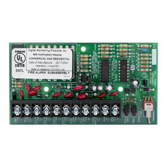
MODEL 865
Figure 1: 865 Module
DESCRIPTION
The 865 NAC module provides
Style W or X supervision for
ground faults, opens, and shorts
on notification appliance circuits
connected to fire alarm control
panels. The 865 is suitable for use
with 2 or 4-wire circuits.
The module also includes a Trouble
LED, Ground Fault LED, and a set of
Normally Closed Trouble contacts
to indicate off normal conditions.
Additionally, the module includes
a Bell Silence switch for use during
testing or service.
Connect a maximum 5 Amp,
12 or 24 VDC regulated, power
limited power supply listed for Fire
Protective Signals to the module to
support alarm power requirements
beyond the panel alarm output
capacity.
Compatibility
•
XT30/XT50 Series panels
•
XR150/XR550 Series panels
What is Included?
•
One 865 NAC Module
•
One Model 308 10k Ohm Resistor
with Leads
•
Hardware Pack
1
NORMAL
BELL
SILENCE
TRBL
GND
FAULT
1
AUX
PWR
2
GND
3
ALARM
INPUT
4
BELL
PWR +
INPUT
5
BELL
PWR -
INPUT
6
BELL A+
OUTPUT
7
BELL A-
OUTPUT
8
BELL B+
OUTPUT
9
BELL B-
OUTPUT
10
BELL
TRBL
11
BELL
TRBL
2
MOUNT THE MODULE
The module can be mounted in a
DMP enclosure using the standard
3-hole mounting pattern. Refer
to Figure 2 as needed during
installation.
1.
Hold the plastic standoffs
against the inside of the
enclosure side wall.
2.
Insert the included Phillips
head screws from the
outside of the enclosure into
the standoffs. Tighten the
screws.
3.
Carefully snap the module
onto the standoffs.
WIRE THE MODULE
Caution: Disconnect all power from the panel before wiring
the module. Failure to do so may result in equipment damage
or personal injury.
For power connections, use 22 AWG or larger wire. Refer to
Figure 3 and Figure 4 when wiring the module.
1.
Connect module Terminal 1 to panel Terminal 7.
2.
Connect module Terminal 2 to panel Terminal 10.
3.
Connect module Terminal 3 to panel Terminal 5.
4.
Wire power supply positive to module Terminal 4.
5.
Wire power supply negative to module Terminal 5.
6.
If powering the NACs from the control panel, connect a
jumper between module Terminals 3 and 4 and between
Terminals 2 and 5. For supervised circuits, ground fault is
detected at 0 (zero) Ohms.
7.
For Style W connections, wire module Terminals 6-11
as shown in Figure 3. Install the included 10k Ohm EOL
resistor across Bell Output A + and Bell Output A –.
8.
For Style X connections, wire module Terminals 6-11 as
shown in Figure 4. Trouble contacts are connected to a
zone on the panel to indicate NAC trouble or ground faults.
The common relay is rated 30 VDC @ 1 Amp, resistive.
9.
For Style W and Style X circuits, install a jumper on the
Bell Ground Header. The jumper also disables the alarm
bell output in the event of a ground fault on either side of
the notification circuit.
1
2
3
Figure 2: Standoff and Module
Installation
Advertisement
Table of Contents

Related Manuals for DMP Electronics 865


Summary of Contents for DMP Electronics 865
- Page 1 Carefully snap the module on notification appliance circuits onto the standoffs. connected to fire alarm control panels. The 865 is suitable for use with 2 or 4-wire circuits. The module also includes a Trouble LED, Ground Fault LED, and a set of Normally Closed Trouble contacts Figure 2: Standoff and Module...
- Page 2 Normal position to return the module to normal operation. LED Operation • Trouble: Lights during an open, short, or short-to-ground on the indicating circuit. • Ground Fault: Lights during a short-to-ground on the indicating circuit. 865 STYLE W/X Accessories BELL POWER NORMAL GROUNDED AT PANEL...
Need help?
Do you have a question about the 865 and is the answer not in the manual?
Questions and answers