DMP Electronics 1134 Installation And Programming Manual
Wireless wiegand module
Hide thumbs
Also See for 1134:
- Installation and programming manual (44 pages) ,
- Installation and programming manual (44 pages)
Table of Contents
Advertisement
Quick Links
Advertisement
Table of Contents

Related Manuals for DMP Electronics 1134


Summary of Contents for DMP Electronics 1134
- Page 1 1134 Wireless Wiegand Module INSTALLATION AND PROGRAMMING GUIDE...
-
Page 3: Table Of Contents
TABLE OF CONTENTS About the 1134 ..........1 Program the 1134 Options ....... 15 Power Supply ............1 Program Start Display ........15 Zone Terminals ............1 Serial Number Display ........15 Annunciators ............1 Initialization Option ...........15 LED Indicators ............1 Initialize Confirm Option .........16... - Page 4 No Communication with Panel ....24 Remove Keypad ..........25 Public Card Formats ....... 26 Product Specifications ......27 Readers and Credentials ......28 FCC Information ........30 Industry Canada Information ....31...
-
Page 5: About The 1134
ABOUT THE 1134 The 1134 Wireless Wiegand Module allows you to use the powerful built-in access control capability of DMP panels. DMP panels provide access control, arming, and disarming using proximity, mag-stripe, biometric or other Wiegand-output authentication devices. The 1134 connects and operates wirelessly with DMP panels. A keypad may be plugged directly into the 1134 for local programming. -
Page 6: Led Survey
FORM C RELAY LED SURVEY The 1134’s Form C relay draws up to 35 mA of The 1134 provides a Survey LED capability to current. Refer to the NC/C/NO (Dry Contact allow one person to confirm communication with Relay) and the Isolation Relay sections in this the wireless receiver while the cover is removed. -
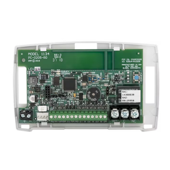
Page 7: Pcb Features
LED Survey Reset Button Keypad Dry/Wet Programming Contact RESET TAMPER Header DISABLE RED WHT GRN BLK PROG Power Wiegand Status Zones Door Relay Supply Inputs Indicator Terminal Outputs Figure 1: PCB Features Digital Monitoring Products, Inc. 1134 Installation and Programming Guide... -
Page 8: Program The 1134
Note: Panel version 191 or higher software is required. 7. Enter the eight-digit SERIAL#:- and press CMD. Note: Enter the Type 14 serial number found on the 1134 PCB or by connecting a keypad to the header on the 1134. -
Page 9: Part 2: Zone Information
5. Select YES when WIRELESS? displays. 6. Enter the eight-digit SERIAL#:- and press CMD. Note: Enter the Type 08 serial number found on the 1134 PCB or by connecting a keypad to the header on the 1134. 7. Enter the CONTACT number being used. -
Page 10: Install The 1134
INSTALL THE 1134 MOUNT THE 1134 The 1134 comes in a high-impact plastic housing that you can mount directly to a wall, backboard, or other flat surface. For easy installation, the back and ends of the 1134 housing have wire entrances. The back also contains multiple mounting holes that allow you to mount the 1134 on a single-gang switch box. -
Page 11: Wire The Electronic Lock
Use a power supply to power magnetic locks. See Figure 3. You can power door strikes either from a power supply (DRY contact) or from the 1134 (WET contact). See Figures 4a and 4b for door strike wiring. - Page 12 When the jumper on the 1134 is set to WET, the C terminal will pass 12 VDC though the C terminal. No additional power supply is needed. See Figure 4b. Normally Open RED WHT GRN BLK – Model 333 DC Door Strike Suppressor...
-
Page 13: Isolation Relay
12/24 VDC – Model 333 Magnetic Lock Supply Power Suppressor Model 333 – Supply Suppressor Figure 5: Magnetic Lock with Figure 6: Door Strike with an Isolation Relay an Isolation Relay Digital Monitoring Products, Inc. 1134 Installation and Programming Guide... -
Page 14: Install The 333 Suppressor
Use the included 333 suppressor with the 1134 to suppress any surges caused by energizing a magnetic lock or door strike. Install the 333 across the 1134 C (common) and NO (normally open) or NC (normally closed) terminals. If the device being controlled by the relay is connected to the NO and C terminals, install the suppressor on the NO and C terminals. -
Page 15: Wire The Zone Terminals
See the table below and Figure 8 for more information on wiring the zone terminals. ZONE # RECOMMENDED DEVICE Any burglary device Door Contact REX (PIR or Button) Any burglary device Table 1: 1134 Zone Uses Digital Monitoring Products, Inc. 1134 Installation and Programming Guide... - Page 16 Zone 1 1K EOL Zone 2 1K EOL Zone 3 1K EOL 1K EOL Zone 4 RED WHT GRN BLK Figure 8: 1134 Zone Terminal Wiring 1134 Installation and Programming Guide Digital Monitoring Products, Inc.
-
Page 17: Connect A Card Reader
CONNECT A CARD READER (optional) The 1134 provides direct 12/24 VDC, 200 mA output to the reader on the RED terminal connection. Figure 9 shows a reader with wire colors RED, WHT, GRN, and BLK connecting to terminals 1, 2, 3, and 4. - Page 18 Card Reader Shield Yellow Orange/Brown Black (GND) Green (Data 0) White (Data 1) Red (12/24VDC) RED WHT GRN BLK PROG Figure 9: Card Reader Wiring 1134 Installation and Programming Guide Digital Monitoring Products, Inc.
-
Page 19: Program The 1134 Options
PROGRAM THE 1134 OPTIONS When you program the 1134, you can use a keypad connected to the 1134 programming header and set to address 1. For 12 V applications, connect the keypad to the module using a Model 330 4-wire harness. For 24 V applications, connect the keypad to the module using a Model 330-24 4-wire programming harness with in-line resistor. -
Page 20: Initialize Confirm Option
If zone 2 restores prior to the end of the programmed time, the piezo silences. If the zone does not restore before the programmed time, the 1134 ends the bypass and indicates the open or short zone condition to the panel. -
Page 21: Zone 2 Bypass Time
Selecting NO leaves the relay on when zone 2 changes state. Turning off the relay at Door Closed allows a long strike time to be automatically ended and relocks the door. The default is NO. Digital Monitoring Products, Inc. 1134 Installation and Programming Guide... -
Page 22: Activate Zone 3 Request To Exit
2 bypass entry/exit timer. After the programmed number of seconds, the relay restores the door to its locked state. The 1134 module provides a bypass-only option for REX on zone 3. When zone 3 OPENS from a NORMAL state, only a bypass occurs: the on-board relay does not activate. -
Page 23: Zone 3 Rex Strike Time
NO YES SPEAKER? as alarm and trouble annunciations. Select NO to turn the speaker off for all operations. This does not affect remote annunciator open collector (RA) operation. The default is NO. Digital Monitoring Products, Inc. 1134 Installation and Programming Guide... -
Page 24: Custom Card Definitions
Select 8 if you would like to program a DMP card format. See Public Card Formats for some publicly available card formats that can be used with the 1134. Other private or custom formats may also be compatible. Please contact the credential supplier or manufacturer for the bit structure. -
Page 25: Wiegand Code Length
An access card contains data bits for a site code, user code, and start/stop/parity bits. The starting position, location, and code length must be determined and programmed into the keypad. See Figure 13. Digital Monitoring Products, Inc. 1134 Installation and Programming Guide... -
Page 26: Site Code Position And Length
In addition to user code verification, door access is only granted when any one site code programmed at the SITE CODE ENTRY option matches the site code received in the Wiegand string. 1134 Installation and Programming Guide Digital Monitoring Products, Inc. -
Page 27: Site Code Display
CMD. NUMBER OF USER CODE DIGITS NO OF USER CODE The 1134 module recognizes user codes from 4-12 digits long. Press DIGITS: any top row select key or area to enter a user code digit length. This number must match the user code number length being programmed in the panel. -
Page 28: No Communication With Panel
Press the first select key or area to choose LAST (Keep Last State) NO COMM WITH PNL — The relay remains in the same state and does not change when LAST communication is lost. 1134 Installation and Programming Guide Digital Monitoring Products, Inc. -
Page 29: Remove Keypad
REMOVE KEYPAD The REMOVE KEYPAD option continually displays with no time out while the keypad remains connected to the 1134 module after programming is finished. After five seconds, the 1134 module piezo continually sounds if the keypad remains connected and programming is finished. -
Page 30: Public Card Formats
CODE CODE LENGTH POSITION LENGTH POSITION LENGTH DIGITS H10301 26 BIT H10302 37 BIT W/FAC H10304 37 BIT W/O FAC FARPOINTE 39 BIT CORPORATE 1000 35 BIT CORPORATE 1000 48 BIT 1134 Installation and Programming Guide Digital Monitoring Products, Inc. -
Page 31: Product Specifications
220 mA (includes 200 mA for proximity reader) Peak 230 mA (includes 200 mA for proximity reader) Reader Current up to 200 mA Zones 5 VDC, 2 mA max Dimensions 4.5 W x 2.75 H x 1.75 D in 11.43 W x 7 H x 4.45 D cm Weight 8 oz .23 kg Digital Monitoring Products, Inc. 1134 Installation and Programming Guide... -
Page 32: Readers And Credentials
PROXPOINT® PLUS 1346 PROXKEY III® PROXIMITY READER ACCESS DEVICE PP-5355 PROXPRO PROXIMITY 1351 PROXPASS® READER WITH KEYPAD PR-5455 PROXPRO® II PROXIMITY 1386 ISOPROX II® CARD READER TL-5395 THINLINE II® PROXIMITY READER 1134 Installation and Programming Guide Digital Monitoring Products, Inc. - Page 33 DC1-1 FARPOINTE CLAMSHELL READER SMARTCARD DELTA5 FARPOINTE SMARTCARD DM1-3 FARPOINTE IMAGEABLE READER SMARTCARD DELTA5.3 FARPOINTE SMARTCARD FARPOINTE MIFARE® READER DESFIRE® EV1 SMARTCARD DELTA6.4 FARPOINTE SMARTCARD READER DK1-3 FARPOINTE KEY FOB SMARTCARD Digital Monitoring Products, Inc. 1134 Installation and Programming Guide...
-
Page 34: Fcc Information
Increase the separation between the equipment and receiver. • Connect the equipment into an outlet on a circuit different from that to which the receiver is connected. • Consult the dealer or an experienced radio/TV technician for help. 1134 Installation and Programming Guide Digital Monitoring Products, Inc. -
Page 35: Industry Canada Information
L’exploitation est autorisée aux deux conditions suivantes: l’appareil ne doit pas produire de brouillage, et 2. l’utilisateur de l’appareil doit accepter tout brouillage radioélectrique subi, même si le brouillage est susceptible d’en compromettre le fonctionnement. Digital Monitoring Products, Inc. 1134 Installation and Programming Guide... - Page 36 LT-1889 19134 © 2019 Digital Monitoring Products, Inc.
Need help?
Do you have a question about the 1134 and is the answer not in the manual?
Questions and answers