Table of Contents
Advertisement
Quick Links
Advertisement
Table of Contents

Related Manuals for DMP Electronics 867 Style W


Summary of Contents for DMP Electronics 867 Style W
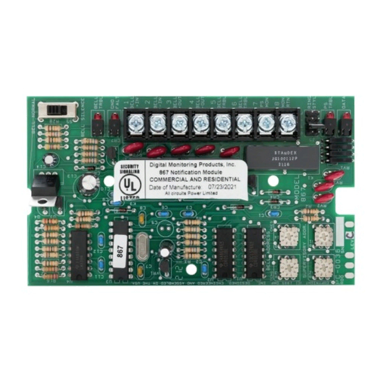
- Page 1 INSTALLATION GUIDE 867 Style W LX-Bus Notification Module...
- Page 2 GET STARTED The 867 module provides one supervised Style W notification appliance circuit for powering polarized 12 or 24 VDC fire notification devices on XR150/XR550 Series panels. The module connects to the panel LX‑Bus and provides ground fault, open, and short condition supervision on the notification circuit. The module has four LEDs to indicate circuit trouble and ground fault conditions, as well as power supply and data monitoring.
- Page 3 INSTALLATION Mount the Module The module can be mounted in a DMP enclosure using the standard 3‑hole mounting pattern. Refer to Figure 1 as needed during installation. Hold the plastic standoffs against the inside of the enclosure side wall. Insert the included Phillips head screws from the outside of the enclosure into the standoffs.
- Page 4 Select a Bell Ring Style The 867 module allows you to specify the cadence of the bell output with the Ring Style header. To select a bell ring style, place a jumper across the two appropriate pins on the header as shown in Figure 2. For more information, refer to Table 2.
- Page 5 ADDITIONAL INFORMATION Wiring Specifications DMP recommends using 18 or 22 AWG for all LX‑Bus and Keypad Bus connections. The maximum wire distance between any module and the DMP Keypad Bus or LX‑Bus circuit is 1,000 feet. To increase the wiring distance, install an auxiliary power supply, such as a DMP Model 505‑12.
- Page 6 SPECIFICATIONS Operating Voltage LX‑Bus 8.0 to 15.0 VDC Operating Current LX‑Bus 30 mA maximum Bell Power 30 mA standby, 86 mA maximum Alarm Switching Current 5 Amps @ 12 or 24 VDC CERTIFICATIONS ▶ California State Fire Marshal (CSFM) ▶ FCC Certified Part 15 ▶...
- Page 7 FCC Information This device complies with Part 15 of the FCC Rules. Operation is subject to the following two conditions: This device may not cause harmful interference, and This device must accept any interference received, including interference that may cause undesired operation. Changes or modifications made by the user and not expressly approved by the party responsible for compliance could void the user’s authority to operate the equipment.
Need help?
Do you have a question about the 867 Style W and is the answer not in the manual?
Questions and answers