Advertisement
Quick Links
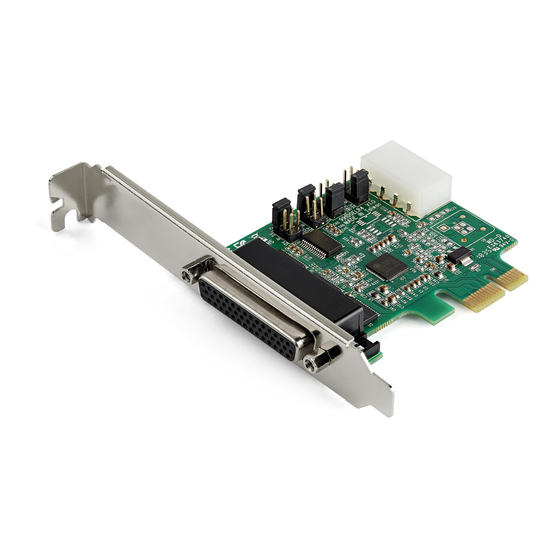
4-Port PCI Express RS232 Serial Card - 16950 UART
Product Diagram (PEX4S953 and PEX4S953LP)
1
3
4
Port
• Connect the 4-Port DB9 Break-out Cable to connect
1
Break-out Cable Port
up to 4 Serial Devices
• Attach the Bracket to the PCI Express Serial Card
2
Stand-offs
• Secure the 4-Port DB9 Break-out Cable to the
Break-out Cable Port
3
Bracket
• Attach the PCI Express Serial Card to the Computer
• Connect the PCI Express Serial Card to the
PCI Express Bus
4
Computer Motherboard
Connector
• Configure the individual Serial Connector power
5
Jumpers
settings
6
• Used to connect an LP4 Power Source
LP4 Power Connector
To view manuals, FAQs, videos, drivers, downloads, technical drawings, and more, visit www.startech.com/support.
2
5
6
Function
Requirements
For the latest requirements please visit:
www.startech.com/PEX4S953
- or -
www.startech.com/PEX4S953LP.
• PCIe Slot
• Needle-Nose Pliers
• (Optional) LP4 Power Source
Installation
WARNING!
PCI Express Serial Cards can be severely damaged by static electricity. Make sure
that you are properly grounded before you open the Computer Case or touch the
PCI Express Serial Card. You should wear an Anti-Static Strap when you install
any computer component. If an Anti-Static Strap isn't available, discharge any
built-up static electricity by touching a large Grounded Metal Surface for several
seconds. Only handle the PCI Express Serial Card by its edges and don't touch
the gold connectors.
Jumper Configuration
Note: This PCI Express Serial Card is specially designed to allow for power output
from the ninth pin of the Serial Connector(s) for Serial Devices that support power
over serial. Jumper configuration is a requirement when connecting Serial Devices
that require power through a Serial Connector.
The Jumper can be moved into one of three different positions in order to set the
power output voltage for the Serial Connector. The default setting for the Jumpers
is RI, no power. The LP4 Power Connector must be connected after configuring the
Jumper to 5V or 12V of power. To configure the Jumper, complete the following:
1. Ensure the Computer Power is Off.
2. Locate the Jumper for Port One and carefully remove the Jumper. Lift the Jumper
straight up and off of the PCI Express Serial Card.
Notes: The Jumper is located on the right hand side, labeled as Port 1 on the
Printed Circuit Board.
Always hold the Card by the edges.
3. Determine the power setting that is required for Port One.
4. Position the Jumper over the set of Pins that correspond with the desired Serial
Connector Power Setting. See Figure 1 to determine where the Jumper should be
positioned.
Quick-Start Guide
Manual Revision: October 31, 2019
Advertisement

Subscribe to Our Youtube Channel
Related Manuals for StarTech.com PEX4S953


Summary of Contents for StarTech.com PEX4S953
- Page 1 Connector Power Setting. See Figure 1 to determine where the Jumper should be Jumpers settings positioned. • Used to connect an LP4 Power Source LP4 Power Connector To view manuals, FAQs, videos, drivers, downloads, technical drawings, and more, visit www.startech.com/support. Manual Revision: October 31, 2019...
- Page 2 StarTech.com. Where they occur these references are for illustrative purposes only 45 Artisans Cres 2500 Creekside Unit B, Pinnacle 15 ES: es.startech.com and do not represent an endorsement of a product or service by StarTech.com, or an endorsement of the product(s) to which Gowerton Rd, London, Ontario Parkwy NL: nl.startech.com this manual applies by the third-party company in question.
Need help?
Do you have a question about the PEX4S953 and is the answer not in the manual?
Questions and answers