
Related Manuals for Hill-Rom DuraStar Series


Summary of Contents for Hill-Rom DuraStar Series
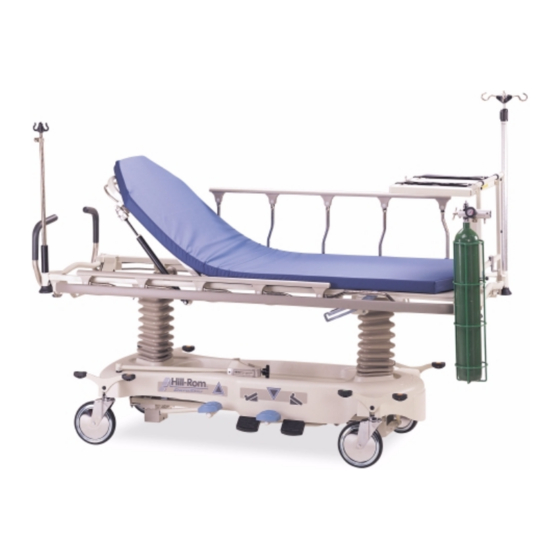
- Page 1 SERVICE MANUAL DuraStar™ Series Stretcher From Hill-Rom Product No. P8005, P8035 For Parts or Technical Assistance man268 USA (800) 445-3720 Canada (800) 267-2337 International: Contact your distributor.
- Page 2 DuraStar™ Series Stretcher Service Manual Revisions Revision Letter Pages Affected Date Original Issue November, 1999 man268 DuraStar™ Series Stretcher Service Manual (man268) Page i...
- Page 3 Velcro® is a registered trademark of Velcro Industries, BV (a Dutch corporation). The information contained in this manual is subject to change without notice. Hill-Rom makes no commitment to update or keep current, the information contained in this manual. The only product warranty intended by Hill-Rom is the express, written warranty accompanying the bill of sale to the original purchaser.
-
Page 4: Table Of Contents
Table of Contents Chapter 1: Introduction Purpose ............1 - 3 Audience . - Page 5 Table of Contents Regulations, Standards, and Codes....... . . 1 - 14 Stretcher .
- Page 6 Table of Contents DuraStar™ Fixed Height Stretcher Function Checks..... . . 2 - 7 Brake/Steer Function ..........2 - 7 Siderail Function.
- Page 7 Table of Contents Caster ............4 - 16 Removal .
- Page 8 Table of Contents Liquid Oxygen Tank Holder—P273........5 - 37 Chart Holder—P361 .
- Page 9 Table of Contents Oxygen Tank Holder ..........7 - 11 Installation .
- Page 10 Chapter 1 Introduction Chapter Contents Purpose ............1 - 3 Audience .
- Page 11 Chapter 1: Introduction Sleep Surface ..........1 - 14 IV Pole Accommodation .
-
Page 12: Chapter 1: Introduction
Purpose Chapter 1: Introduction Purpose This manual provides requirements for the DuraStar™ Series Stretcher normal operation and maintenance. It also includes parts lists (in chapter 5) for ordering replacement components. Audience This manual is intended for use by only facility-authorized personnel. Failure to observe this restriction can result in severe injury to people and serious damage to equipment. -
Page 13: Chapter 6: General Procedures
Organization Chapter 1: Introduction Chapter 6: General Procedures Cleaning, preventive maintenance, and other general procedures are described in this chapter. Chapter 7: Accessories A list of additional products, that can be used in conjunction with the DuraStar™ Series Stretcher, is available in chapter 7. Installation procedures for these accessories are also included. -
Page 14: Typographical Conventions
Typographical Conventions Chapter 1: Introduction Typographical Conventions This manual contains different typefaces and icons designed to improve readability and increase understanding of its content. Note the following examples: • Standard text—used for regular information. • Boldface text—emphasizes a word or phrase. •... -
Page 15: Introduction
Introduction Chapter 1: Introduction Introduction General Description The DuraStar™ Series Stretcher is available in two models: fixed height and hydraulic. Both models are mounted on casters to move easily, have pneumatic-assisted back sections that rise to 90°, and have non-marring bumpers on corners and siderails. - Page 16 Introduction Chapter 1: Introduction Figure 1-5. Pneumatic-assisted Back Section m268_005 NOTE: The hydraulic model is shown. DuraStar™ Series Stretcher Service Manual (man268) Page 1 - 7...
- Page 17 Introduction Chapter 1: Introduction Figure 1-6. Hilow Positions of Hydraulic Model m268_006 Page 1 - 8 DuraStar™ Series Stretcher Service Manual (man268)
- Page 18 Introduction Chapter 1: Introduction Figure 1-7. Trendelenburg/Reverse Trendelenburg Positions for Hydraulic Model m268_007 DuraStar™ Series Stretcher Service Manual (man268) Page 1 - 9...
- Page 19 Introduction Chapter 1: Introduction Figure 1-8. Hydraulic Stretcher Back Section m268_008 Page 1 - 10 DuraStar™ Series Stretcher Service Manual (man268)
- Page 20 Introduction Chapter 1: Introduction Figure 1-9. Fixed Height Stretcher Back Section m268_009 DuraStar™ Series Stretcher Service Manual (man268) Page 1 - 11...
-
Page 21: Specifications
Specifications Chapter 1: Introduction Specifications Physical Description See table 1-1 on page 1-12 for DuraStar™ Series Stretcher specifications. Table 1-1. Specifications Feature Dimension Overall Length 83" (211 cm) Overall width 32" (81 cm) Siderail height above sleep surface 14" (35 cm) Mattress size 26"... -
Page 22: Stretcher Back Section Inclination
Specifications Chapter 1: Introduction Stretcher Back Section Inclination Both models of the DuraStar™ Series Stretcher are mechanized so that the attendant can raise or lower the back section by squeezing the release handle located under the back section. The back section can be elevated from 0° to 90°. -
Page 23: Bumpers
Specifications Chapter 1: Introduction Bumpers Both stretcher models are equipped with non-marring, rolling, disk bumpers on the corners and non-marring, bumper material around the perimeter of the siderails whether they are raised or stored. Sleep Surface The stretcher is equipped with a metal sleep surface that accommodates Velcro®... -
Page 24: Model Identification
Model Identification Chapter 1: Introduction Model Identification See table 1-2 on page 1-15 for DuraStar™ Series Stretcher model identification. Table 1-2. Model Identification Model Number Description P8005 DuraStar™ Hydraulic Stretcher P8035 DuraStar™ Fixed Height Stretcher General Operation The DuraStar™ Series Stretcher is a mechanically operated stretcher. The following paragraphs explain the basic operation of this stretcher. -
Page 25: Back Articulation
General Operation Chapter 1: Introduction Back Articulation WARNING: Ensure you fully control the lift of the back section. The back section could raise quickly with little or no weight on it, and personal injury could occur. Raising the Back Section •... -
Page 26: Trendelenburg/Reverse Trendelenburg Operation
General Operation Chapter 1: Introduction Trendelenburg/Reverse Trendelenburg Operation The Trendelenburg/Reverse Trendelenburg pedals are located on both sides of the hydraulic stretcher. The stretcher must be in a raised position to achieve Trendelenburg/Reverse Trendelenburg positions. Trendelenburg Press the foot pedal marked with the graphic showing Trendelenburg until the desired angle is reached. -
Page 27: Central Brake And Steer
General Operation Chapter 1: Introduction Central Brake and Steer The foot caster on the patient’s left side locks parallel with the length of the stretcher to provide steering capability. Steer • Press down on the green steer pedal. • To release the locked steering caster, press the orange brake pedal until the pedal is parallel to the floor. -
Page 28: Safety Tips
Safety Tips Chapter 1: Introduction Safety Tips WARNING: Establish policies and procedures to train and educate your staff on the stretcher operation. Personnel should never have their entire body below the sleep surface and within the confines of the stretcher. If service personnel need to get under the stretcher, block up the hilow portion as an added precaution. - Page 29 Safety Tips Chapter 1: Introduction WARNING: Ensure you fully control the lift of the back section. The back section could rise quickly with little or no weight on it, and personal injury could occur. WARNING: Do not use retaining rings that are overextended. Personal injury could occur.
- Page 30 Safety Tips Chapter 1: Introduction WARNING: When the stretcher is occupied, ensure the siderails are in the full upright and locked position before gliding the patient platform. Failure to do so could result in personal injury. WARNING: Adhere to the “Infection Control Policies and Procedures” outlined in the Safety Coordinator Reference Guide.
- Page 31 Safety Tips Chapter 1: Introduction CAUTION: Leave the cylinder rod, hold-down assembly in place until the cylinder is secured to the frame assembly. Equipment damage can occur. CAUTION: Do not rotate the gas spring, cylinder rod with a clamping device. Damage to the cylinder rod can occur.
-
Page 32: Warning And Caution Labels
Warning and Caution Labels Chapter 1: Introduction Warning and Caution Labels Figure 1-10. Warning and Caution Labels m268_142 m268_169 DuraStar™ Series Stretcher Service Manual (man268) Page 1 - 23... - Page 33 Warning and Caution Labels Chapter 1: Introduction NOTES: Page 1 - 24 DuraStar™ Series Stretcher Service Manual (man268)
- Page 34 Chapter 2 Troubleshooting Procedures Chapter Contents Getting Started ........... . 2 - 3 Initial Actions .
-
Page 35: Chapter 2: Troubleshooting Procedures
Chapter 2: Troubleshooting Procedures NOTES: Page 2 - 2 DuraStar™ Series Stretcher Service Manual (man268) -
Page 36: Getting Started
(replacing or adjusting a part, seating a connector, etc.). Perform Final Actions after the Function Checks to verify the repair. If troubleshooting procedures do not isolate the problem, call Hill-Rom Technical Support at (800) 445-3720 for assistance. Initial Actions Use Initial Actions to gather information from operators concerning problems with the DuraStar™... -
Page 37: Durastar™ Hydraulic Stretcher Function Checks
DuraStar™ Hydraulic Stretcher Function Checks Chapter 2: Troubleshooting Procedures 2. Ask that person to demonstrate or explain the problem. The problem can be duplicated. ↓ → Go to “DuraStar™ Hydraulic Stretcher Function Checks” on page 2-4 or “DuraStar™ Fixed Height Stretcher Function Checks”... -
Page 38: Hilow Function
DuraStar™ Hydraulic Stretcher Function Checks Chapter 2: Troubleshooting Procedures 5. Put the stretcher in the neutral position. The pedal seats in that position, and all four casters rotate and roll freely. ↓ → Go to RAP 2.3. Hilow Function 6. Put a 40 lb (18 kg) weight on the stretcher. Press the right side pump pedal 24 times to raise the stretcher to the high position. -
Page 39: Trendelenburg/Reverse Trendelenburg Function
DuraStar™ Hydraulic Stretcher Function Checks Chapter 2: Troubleshooting Procedures Trendelenburg/Reverse Trendelenburg Function 11. Press the pump pedal 24 times to raise the stretcher to the high position. Press the Trendelenburg pedal. The head end of the stretcher lowers smoothly. ↓ →... -
Page 40: Durastar™ Fixed Height Stretcher Function Checks
DuraStar™ Fixed Height Stretcher Function Checks Chapter 2: Troubleshooting Procedures DuraStar™ Fixed Height Stretcher Function Checks 1. Initial Actions have been performed. ↓ → Go to “Initial Actions” on page 2-3. Brake/Steer Function 2. Put the stretcher in the brake position. The brake pedal seats in that position, and none of the four casters roll or rotate. -
Page 41: Optional Push Handle Function
Final Actions Chapter 2: Troubleshooting Procedures Optional Push Handle Function 7. Raise the push handles. The push handles lock into position. ↓ → Go to RAP 2.8. 8. Lift up on the push handle release latch. The push handles drop into the stored position. -
Page 42: Reduced Braking Ability
“Final Actions” on page 2-8. Otherwise, go to step 5. 5. Another part of the stretcher interferes with the brake/steer mechanism. ↓ → Call Hill-Rom Technical Support at (800) 445-3720. 6. Take appropriate actions to eliminate the interference. This solves the problem. ↓... -
Page 43: Loss Of Corner Steer
2.2 Loss of Corner Steer Chapter 2: Troubleshooting Procedures Loss of Corner Steer 1. The brake/steer pedal locks into the steer position. ↓ → Go to step 3. 2. The corner steer caster locks into position. ↓ → Replace the caster (refer to procedure 4.6). If this solves the problem, go to “Final Actions”... - Page 44 2.2 Loss of Corner Steer Chapter 2: Troubleshooting Procedures 5. Another part of the stretcher interferes with the steering linkages. ↓ → Call Hill-Rom Technical Support at (800) 445-3720. 6. Take appropriate actions to eliminate the interference. This solves the problem. ↓...
-
Page 45: Stretcher Will Not Go Into The Neutral Position
2.3 Stretcher Will Not Go Into the Neutral Position Chapter 2: Troubleshooting Procedures Stretcher Will Not Go Into the Neutral Position 1. The brake/steer pedal locks into the neutral position. ↓ → Go to step 4. 2. The stretcher rolls freely in all directions. ↓... - Page 46 2.3 Stretcher Will Not Go Into the Neutral Position Chapter 2: Troubleshooting Procedures 8. Another part of the stretcher interferes with the brake/steer pedal. ↓ → Call Hill-Rom Technical Support at (800) 445-3720. 9. Take appropriate actions to eliminate the interference. This solves the problem. ↓...
-
Page 47: Reduced Pedal Pumping
2.4 Reduced Pedal Pumping Chapter 2: Troubleshooting Procedures Reduced Pedal Pumping 1. Press the pump pedal 24 times to raise the stretcher to the high position. The stretcher rises to the high position. ↓ → Ensure the pump linkage shoulder bolt (A) and locknut (B) are in place, and check the nut torque of 40 + 8 in-lb (4.5 + 0.9 N·m) (see figure 2-2 on page 2-14). - Page 48 (refer to procedure 4.7). If this solves the problem, go to “Final Actions” on page 2-8. Otherwise, call Hill-Rom Technical Support at (800) 445-3720. 6. Go to “Final Actions” on page 2-8.
-
Page 49: Stretcher Will Not Lower
2.5 Stretcher Will Not Lower Chapter 2: Troubleshooting Procedures Stretcher Will Not Lower 1. When the foot release pedal is pushed, the Trendelenburg offset plunger (D) fully depresses the release pin (B) on the hydraulic cylinder (A) (see figure 2-3 on page 2-16). Figure 2-3. - Page 50 → Replace the hydraulic cylinder at the foot end of the stretcher (refer to procedure 4.7). If this solves the problem, go to “Final Actions” on page 2-8. Otherwise, call Hill-Rom Technical Support at (800) 445-3720. 7. Go to “Final Actions” on page 2-8.
-
Page 51: Siderail Malfunction
2.6 Siderail Malfunction Chapter 2: Troubleshooting Procedures Siderail Malfunction 1. Raise the siderail, but do not allow the latch to lock. The siderail falls without assistance. ↓ → Go to step 4. 2. Torque the lower pivot bolts (A) to 140 + 10 in-lb (15.8 + 1.1 N ·m) (see figure 2-4 on page 2-18). - Page 52 Figure 2-5. Siderail Latch m268_015 5. Another part of the stretcher interferes with the siderail. ↓ → Call Hill-Rom Technical Support at (800) 445-3720. 6. Take appropriate actions to eliminate the interference. This solves the problem. ↓ → Call Hill-Rom Technical Support at (800) 445-3720.
-
Page 53: Stretcher Back Panel Does Not Go Up/Down Correctly
→ Replace the damaged back panel gas spring (refer to procedure 4.3). If this solves the problem, go to “Final Actions” on page 2-8. Otherwise, call Hill-Rom Technical Support at (800) 445- 3720. 3. Go to “Final Actions” on page 2-8. -
Page 54: Push Handle Malfunction
→ Replace the push handles (refer to procedure 7.7). If this solves the problem, go to “Final Actions” on page 2-8. Otherwise, call Hill-Rom Technical Support at (800) 445-3720. 6. Go to “Final Actions” on page 2-8. DuraStar™ Series Stretcher Service Manual (man268) - Page 55 2.8 Push Handle Malfunction Chapter 2: Troubleshooting Procedures NOTES: Page 2 - 22 DuraStar™ Series Stretcher Service Manual (man268)
-
Page 56: Chapter 3: Theory Of Operation
Chapter 3 Theory of Operation Chapter Contents A theory of operation is not available for the DuraStar™ Series Stretcher. DuraStar™ Series Stretcher Service Manual (man268) Page 3 - 1... - Page 57 Chapter 3: Theory of Operation NOTES: Page 3 - 2 DuraStar™ Series Stretcher Service Manual (man268)
- Page 58 Chapter 4 Removal, Replacement, and Adjustment Procedures Chapter Contents Stretcher Siderail Post..........4 - 3 Removal .
-
Page 59: Chapter 4: Removal, Replacement, And Adjustment Procedures
Chapter 4: Removal, Replacement, and Adjustment Procedures Replacement ..........4 - 24 DuraStar™... -
Page 60: Stretcher Siderail Post
4.1 Stretcher Siderail Post Chapter 4: Removal, Replacement, and Adjustment Procedures Stretcher Siderail Post Tools required: Drill T30 Torx® head bit 3/16" drill bit 1/8" pin punch 1/2" open end wrench Hammer 1/2" socket Torque wrench 0-250 in-lb 1/4" socket Ratchet Phillips head screwdriver Removal... -
Page 61: Replacement
4.1 Stretcher Siderail Post Chapter 4: Removal, Replacement, and Adjustment Procedures Replacement 1. Install the new siderail tube into the upper pivot (F). 2. Install the new ratchet rivets (E) into the upper pivot (F). 3. Install the lower pivot bolt (D) into the bent bottom rail extension (B) and torque to 140 + 10 in-lb (15.8 + 1.1 N ·m) . -
Page 62: Stretcher Siderail Latch
4.2 Stretcher Siderail Latch Chapter 4: Removal, Replacement, and Adjustment Procedures Stretcher Siderail Latch Tools required: T30 Torx® head bit Ratchet Torque wrench 0-250 in-lb 1/4" socket Parts required: 46362 Lower pivot bolt 6515201 Siderail latch 48645 Shoulder bolt latch Removal 1. -
Page 63: Replacement
4.2 Stretcher Siderail Latch Chapter 4: Removal, Replacement, and Adjustment Procedures 4. Using the ratchet and the T30 Torx® head bit, remove and discard the lower pivot bolt (G), roller spacer (H), latch bushing (I), and latch (E) from the rail assembly. Replacement 1. - Page 64 4.2 Stretcher Siderail Latch Chapter 4: Removal, Replacement, and Adjustment Procedures 8. Install the siderail trim strip (C) onto the bent bottom rail extension (B). 9. Install the bottom rail end caps (A) onto the bent bottom rail extension (B). 10.
-
Page 65: Stretcher Back Panel Gas Spring
4.3 Stretcher Back Panel Gas Spring Chapter 4: Removal, Replacement, and Adjustment Procedures Stretcher Back Panel Gas Spring Tools required: Screwdriver Pliers Retaining ring removal/installation tool 17 mm wrench Removal WARNING: Ensure you fully control the lift of the back section. The back section could rise quickly with little or no weight on it, and personal injury could occur. -
Page 66: Replacement
4.3 Stretcher Back Panel Gas Spring Chapter 4: Removal, Replacement, and Adjustment Procedures CAUTION: Do not overextend the retaining rings. If the retaining rings are overextended, use new ones for the installation. Equipment damage can occur. 3. Using the retaining ring removal/installation tool, remove the retaining rings (A) and (F) from the top and bottom headed pins (B) and (E). -
Page 67: Adjustment
4.3 Stretcher Back Panel Gas Spring Chapter 4: Removal, Replacement, and Adjustment Procedures 6. Install the push nut (D) onto the solid rivet (C). 7. Check the adjustment on the release handle (see figure 4-4 on page 4-10). Figure 4-4. Release Handle Adjustment m268_055 Adjustment 1. - Page 68 4.3 Stretcher Back Panel Gas Spring Chapter 4: Removal, Replacement, and Adjustment Procedures 5. Remove the retaining ring (F) and the headed pin (E) located at the bottom of the spring. 6. Rotate the spring clockwise or counterclockwise to adjust. 7.
-
Page 69: Durastar™ Hydraulic Stretcher Upper Frame
4.4 DuraStar™ Hydraulic Stretcher Upper Frame Chapter 4: Removal, Replacement, and Adjustment Procedures DuraStar™ Hydraulic Stretcher Upper Frame Tools required: 9/16" socket Ratchet Torque wrench 0-250 in-lb Blue Loctite® adhesive (P/N SA3618) Rubber mallet/hammer Removal 1. Raise the stretcher to the high position. 2. -
Page 70: Replacement
4.4 DuraStar™ Hydraulic Stretcher Upper Frame Chapter 4: Removal, Replacement, and Adjustment Procedures WARNING: Two people are required for this procedure. If you do not use two people, personal injury could occur. CAUTION: Be careful not to damage the base shroud when you remove the upper frame assembly. -
Page 71: Base Shroud Cover
4.5 Base Shroud Cover Chapter 4: Removal, Replacement, and Adjustment Procedures Base Shroud Cover Tools required: None Removal 1. For the DuraStar™ Hydraulic Stretcher, remove the upper frame assembly (refer to procedure 4.4). For the DuraStar™ Fixed Height Stretcher, remove the upper frame assembly (refer to procedure 4.8). NOTE: The shroud is held in place with Velcro®... -
Page 72: Replacement
4.5 Base Shroud Cover Chapter 4: Removal, Replacement, and Adjustment Procedures Replacement NOTE: The shroud is held in place with Velcro® strips. 1. Install the shroud (A), bellows (B), and the bellows attachment (C). 2. Ensure the shroud cover seats firmly into position and makes contact with all Velcro®... -
Page 73: Caster
4.6 Caster Chapter 4: Removal, Replacement, and Adjustment Procedures Caster Tools required: Hammer 8" x 2" x 4" (20 cm x 5 cm x 10 cm) lumber 5/16" pin punch 7/16" open end wrench Phillips head screwdriver Torque wrench Blue Loctite® adhesive T25 Torx®... - Page 74 4.6 Caster Chapter 4: Removal, Replacement, and Adjustment Procedures Figure 4-7. Shroud Secured to Upper Frame m268_036 DuraStar™ Series Stretcher Service Manual (man268) Page 4 - 17...
- Page 75 4.6 Caster Chapter 4: Removal, Replacement, and Adjustment Procedures 2. Put the stretcher in the steer position by pressing down on the green steer pedal. 3. Remove the screw (B) from the brake/steer link (H) (see figure 4-8 on page 4-18).
-
Page 76: Replacement
4.6 Caster Chapter 4: Removal, Replacement, and Adjustment Procedures WARNING: Two people are required for this procedure. If you do not use two people, personal injury could occur. 9. Using the 8" x 2" x 4" (20 cm x 5 cm x 10 cm) lumber, raise and temporarily block the stretcher to remove the caster. - Page 77 4.6 Caster Chapter 4: Removal, Replacement, and Adjustment Procedures 2. Slide the caster into the base of the stretcher (K) (see figure 4-8 on page 4-18). 3. Using the 7/16" open end wrench, install the caster screw (F) and use blue Loctite®...
-
Page 78: Stretcher Hydraulic Cylinder
4.7 Stretcher Hydraulic Cylinder Chapter 4: Removal, Replacement, and Adjustment Procedures Stretcher Hydraulic Cylinder Tools required: 9/16" socket 5/32" Allen™ wrench 7/16" socket Rubber mallet/hammer 9/16" open end wrench Torque wrench 0-250 in-lb 7/16" open end wrench Ratchet Removal 1. Raise the stretcher to the high position. 2. - Page 79 4.7 Stretcher Hydraulic Cylinder Chapter 4: Removal, Replacement, and Adjustment Procedures WARNING: Ensure you use proper lifting methods. Personal injury can occur. One person can safely lift the upper frame when one end of the upper frame is still secured to the hydraulic cylinder. CAUTION: Be careful not to damage the base shroud when you remove the upper frame assembly.
- Page 80 4.7 Stretcher Hydraulic Cylinder Chapter 4: Removal, Replacement, and Adjustment Procedures Figure 4-11. Hydraulic Cylinder Replacement m268_040 7. Remove the pump linkage shoulder bolt (G) and nut (H) that secures the linkage to the hydraulic cylinder. 8. Using the 7/16" open end wrench, the ratchet, and the 7/16" socket, remove the four locknuts (C), bolts (E), and two washers (F) that secure the cylinder to the foot end support of the lower frame.
-
Page 81: Replacement
4.7 Stretcher Hydraulic Cylinder Chapter 4: Removal, Replacement, and Adjustment Procedures Replacement WARNING: Ensure you use proper lifting methods. Personal injury can occur. The weight of the lower frame, with one end of the upper frame still secured to the hydraulic cylinder, will act as a counterweight during the lifting process. - Page 82 4.7 Stretcher Hydraulic Cylinder Chapter 4: Removal, Replacement, and Adjustment Procedures 9. Check the pump release adjustment (refer to procedure 4.10). 10. Install the base shroud, bellow, and bellow attachment plates over the cylinder (see figure 4-6 on page 4-14). WARNING: Ensure you use proper lifting methods.
- Page 83 4.7 Stretcher Hydraulic Cylinder Chapter 4: Removal, Replacement, and Adjustment Procedures 16. Raise the stretcher to the high position. 17. If more than 24 pumps are required to raise the stretcher to the high position, repeat the purge procedure in step 15 until the stretcher can be raised to the high position with only 24 pumps or less.
-
Page 84: Durastar™ Fixed Height Stretcher Upper Frame
4.8 DuraStar™ Fixed Height Stretcher Upper Frame Chapter 4: Removal, Replacement, and Adjustment Procedures DuraStar™ Fixed Height Stretcher Upper Frame Tools required: 1/4" socket Ratchet Torque wrench 0-250 in-lb 1/4" Allen™ wrench (2) T25 Torx® head bit WARNING: Two people are required for removal, adjustment, and replacement of the upper frame. - Page 85 4.8 DuraStar™ Fixed Height Stretcher Upper Frame Chapter 4: Removal, Replacement, and Adjustment Procedures Figure 4-12. Fixed Height Stretcher Adjustment (Typical Head and Foot) m268_039 2. Using the ratchet and the 1/4" socket, remove the four bolts (A), two plates (K) and nuts (C) that secure the upper frame to the head end weldment (B) (see figure 4-13 on page 4-29).
- Page 86 4.8 DuraStar™ Fixed Height Stretcher Upper Frame Chapter 4: Removal, Replacement, and Adjustment Procedures Figure 4-13. Fixed Height Stretcher Upper Frame Removal/Replacement m268_041 3. Using the ratchet and T25 Torx® head bit, remove the four screws (D) and two foot end clips (E) that secure the upper frame to the foot end weldment (F).
-
Page 87: Replacement
4.8 DuraStar™ Fixed Height Stretcher Upper Frame Chapter 4: Removal, Replacement, and Adjustment Procedures Replacement 1. Put the upper frame onto the base assembly so that the frame is in position, and the holes align on the head end (B) and foot end weldments (F) (see figure 4-13 on page 4-29). - Page 88 4.8 DuraStar™ Fixed Height Stretcher Upper Frame Chapter 4: Removal, Replacement, and Adjustment Procedures Figure 4-14. Fixed Height Upper Frame Height Adjustment m268_042 2. Pull the four height adjustment pins (G) from the opposite end that the screws (H) were removed. 3.
-
Page 89: Caster Brake
4.9 Caster Brake Chapter 4: Removal, Replacement, and Adjustment Procedures Caster Brake Tools required: 3/16" pin punch 0.070" feeler gauge Hammer Adjustment 1. Ensure the brake/steer pedal is in the neutral position. 2. Using the pin punch and hammer, gently spin the brake shoe (A) clockwise to tighten and counterclockwise to loosen (see figure 4-15 on page 4-32). - Page 90 4.9 Caster Brake Chapter 4: Removal, Replacement, and Adjustment Procedures 4. Adjust the gap between the brake shoe and the wheel to 0.073" (1.85 mm) + 0.023" (0.58 mm). 5. Check caster for proper operation. 6. To ensure proper operation of the DuraStar™ Hydraulic Stretcher, perform the “DuraStar™...
-
Page 91: 4.10 Hydraulic Cylinder Release
4.10 Hydraulic Cylinder Release Chapter 4: Removal, Replacement, and Adjustment Procedures 4.10 Hydraulic Cylinder Release Tools required: Torque wrench 0-250 in-lb 1/8" Allen™ wrench Adjustment 1. Push the corresponding release pedal down until the pedal stop comes in contact with the base frame. 2. - Page 92 4.10 Hydraulic Cylinder Release Chapter 4: Removal, Replacement, and Adjustment Procedures 5. Using the torque wrench, torque the screw (B) to 40 + 6 in-lb (4.5 + 0.7 N·m). 6. Check for proper operation of all pedals. 7. To ensure proper operation of the DuraStar™ Hydraulic Stretcher, perform the “DuraStar™...
- Page 93 4.10 Hydraulic Cylinder Release Chapter 4: Removal, Replacement, and Adjustment Procedures NOTES: Page 4 - 36 DuraStar™ Series Stretcher Service Manual (man268)
- Page 94 Chapter 5 Parts List Chapter Contents Warranty ............5 - 3 Service Parts Ordering .
- Page 95 Chapter 5: Parts List NOTES: Page 5 - 2 DuraStar™ Series Stretcher Service Manual (man268)
-
Page 96: Warranty
Replacement of non-technical items will be the responsibility of the customer. If requested by Hill-Rom, products or parts for which a warranty claim is made shall be returned prepaid to Hill-Rom’s factory. - Page 97 Warranty Chapter 5: Parts List NOTES: Page 5 - 4 DuraStar™ Series Stretcher Service Manual (man268)
-
Page 98: Service Parts Ordering
• Product number • Serial number • Part number(s) Hill-Rom also provides a fax number to promptly order parts, request part prices and availability, or follow up on a service order. The fax number is (812) 934-8472. DuraStar™ Series Stretcher Service Manual (man268) - Page 99 RMA packet is included with each order. This packet includes an RMA number, instructions, and a shipping label. If an RMA number is not available, obtain one by phoning Hill-Rom Technical Support at (800) 445-3720. Page 5 - 6...
-
Page 100: Exchange Policy
In some cases, the invoice accompanying the parts will show the full selling price (only for internal use at Hill-Rom). Do not confuse this price with your price. Do not return any parts without an RMA number. When parts/products have been requested to be returned, Hill-Rom will include an RMA packet with the parts/products shipment. -
Page 101: Recommended Spare Parts
Recommended Spare Parts Chapter 5: Parts List Recommended Spare Parts See table 5-1 on page 5-6 for recommended spare parts list to service ten stretchers or more Table 5-1. Recommended Spare Parts. Part number Quantity Description 65144 (8000) Hydraulic cylinder head 46150 (8000) Hydraulic cylinder foot 9022927 (8000) - Page 102 Recommended Spare Parts Chapter 5: Parts List NOTES: DuraStar™ Series Stretcher Service Manual (man268) Page 5 - 9...
-
Page 103: Durastar™ Hydraulic Stretcher Base Assembly
DuraStar™ Hydraulic Stretcher Base Assembly Chapter 5: Parts List DuraStar™ Hydraulic Stretcher Base Assembly Figure 5-2. DuraStar™ Hydraulic Stretcher Base Assembly m268_016 Page 5 - 10 DuraStar™ Series Stretcher Service Manual (man268) - Page 104 DuraStar™ Hydraulic Stretcher Base Assembly Chapter 5: Parts List Table 5-2. DuraStar™ Hydraulic Stretcher Base Assembly Item Number Part Number Quantity Description 3815602 (8000) Hole plug 48653 (8000) Bumper 65084 (8000) Pump/down pedal 4614648 (8000) Pump pedal weldment, lh 61453 (8000) Hydraulic cylinder head 46338 (8000) Split bushing...
- Page 105 DuraStar™ Hydraulic Stretcher Base Assembly Chapter 5: Parts List Item Number Part Number Quantity Description 62050 (8000) Rue ring 46094pl (8000) Reverse Trendelenburg connection tube weldment 65024 (8000) Clevis pin 46148pl (8000) Trendelenburg connection tube weldment 9025806 (8000) Shoulder screw 65142 (8000) Plastic washer (brake/steer) 9023404 (8000)
- Page 106 DuraStar™ Hydraulic Stretcher Base Assembly Chapter 5: Parts List Item Number Part Number Quantity Description 9025828 (8000) Screw 65513 (8000) Bellows attachment plate 65105 (8000) Bellows 4540 (8000) Washer 41459 (8000) Lock washer 9001724H Screw (8000) 6510701 (8000) Base shroud, hydraulic 65312 (8000) DuraStar™...
-
Page 107: Durastar™ Hydraulic Stretcher Upper Frame Assembly
DuraStar™ Hydraulic Stretcher Upper Frame Assembly Chapter 5: Parts List DuraStar™ Hydraulic Stretcher Upper Frame Assembly Figure 5-3. DuraStar™ Hydraulic Stretcher Upper Frame Assembly m268_020 Page 5 - 14 DuraStar™ Series Stretcher Service Manual (man268) - Page 108 DuraStar™ Hydraulic Stretcher Upper Frame Assembly Chapter 5: Parts List Table 5-3. DuraStar™ Hydraulic Stretcher Upper Frame Assembly Item Number Part Number Quantity Description 65149 (8000) Upper frame weldment 46361 (8000) Retaining ring 4603801 (8000) Bumper, upper frame 46019 (8000) Corner shroud, rh 48621 (8000) Screw...
- Page 109 DuraStar™ Hydraulic Stretcher Upper Frame Assembly Chapter 5: Parts List Item Number Part Number Quantity Description 46190 (8000) Head release handle weldment 17291 (8000) Pushnut 46362 (8000) Lower pivot bolt 46022pl (8000) Roller guide 4637504pl Headed pin (8000) 46116 (8000) Wave washer 46334 (8000) Mattress attachment...
- Page 110 DuraStar™ Hydraulic Stretcher Upper Frame Assembly Chapter 5: Parts List NOTES: DuraStar™ Series Stretcher Service Manual (man268) Page 5 - 17...
-
Page 111: Durastar™ Fixed Height Stretcher Base Assembly
DuraStar™ Fixed Height Stretcher Base Assembly Chapter 5: Parts List DuraStar™ Fixed Height Stretcher Base Assembly Figure 5-4. DuraStar™Fixed Height Stretcher Base Assembly m268_017 Page 5 - 18 DuraStar™ Series Stretcher Service Manual (man268) - Page 112 DuraStar™ Fixed Height Stretcher Base Assembly Chapter 5: Parts List Table 5-4. DuraStar™ Fixed Height Stretcher Base Assembly Item Number Part Number Quantity Description 49174 (8000) Pad, brake/steer pedal 491420160 Button, brake pedal (8000) 6514601 (8000) Brake/steer pedal weldment 65298 (8000) Cap plug retainer, brake/steer link 65297 (8000) Cap plug, brake/steer link...
- Page 113 DuraStar™ Fixed Height Stretcher Base Assembly Chapter 5: Parts List Item Number Part Number Quantity Description 6019848 (8000) Head support bolt spacer 6510702 (8000) Base shroud fixed height 63829 (8000) Base label kit 6021150 (8000) Column base weldment, head 4609201pl Hydraulic cylinder bracket washer (8000) 4640101 (8000)
- Page 114 DuraStar™ Fixed Height Stretcher Base Assembly Chapter 5: Parts List NOTES: DuraStar™ Series Stretcher Service Manual (man268) Page 5 - 21...
-
Page 115: Durastar™ Fixed Height Stretcher Upper Frame
DuraStar™ Fixed Height Stretcher Upper Frame Chapter 5: Parts List DuraStar™ Fixed Height Stretcher Upper Frame Figure 5-5. DuraStar™ Fixed Height Stretcher Upper Frame m268_021 Page 5 - 22 DuraStar™ Series Stretcher Service Manual (man268) - Page 116 DuraStar™ Fixed Height Stretcher Upper Frame Chapter 5: Parts List Table 5-5. DuraStar™ Fixed Height Stretcher Upper Frame Item Number Part Number Quantity Description 65149 (8000) Upper frame weldment 46361 (8000) Retaining ring 4603801 (8000) Bumper, upper frame 46019 (8000) Corner shroud, rh 48621 (8000) Screw...
- Page 117 DuraStar™ Fixed Height Stretcher Upper Frame Chapter 5: Parts List Item Number Part Number Quantity Description 9001216 (8000) Truss head rivet 46190 (8000 Head release handle weldment 17291 (8000) Pushnut 46362 (8000) Lower pivot bolt 46022 (8000) Roller guide 4637504pl Headed pin (8000) 46116 (8000)
- Page 118 DuraStar™ Fixed Height Stretcher Upper Frame Chapter 5: Parts List NOTES: DuraStar™ Series Stretcher Service Manual (man268) Page 5 - 25...
-
Page 119: Iv Pole Module Assembly
IV Pole Module Assembly Chapter 5: Parts List IV Pole Module Assembly Figure 5-6. IV Pole Module Assembly m268_022 Page 5 - 26 DuraStar™ Series Stretcher Service Manual (man268) - Page 120 IV Pole Module Assembly Chapter 5: Parts List Table 5-6. IV Pole Module Assembly Item Number Part Number Quantity Description 65235 (8000) Tube 65236 (8000) 9685 (8000) Roll pin 65288 (8000) Sleeve 65237 (8000) Outer tube guide assembly 35775 (8000) Stop pin 2374 (8000) Lock spring...
-
Page 121: Patient Tray-P490
Patient Tray—P490 Chapter 5: Parts List Patient Tray—P490 Figure 5-7. Patient Tray—P490 m268_054 Page 5 - 28 DuraStar™ Series Stretcher Service Manual (man268) - Page 122 Patient Tray—P490 Chapter 5: Parts List Table 5-7. Patient Tray—P490 Item Number Part Number Quantity Description 4640701 (8000) Latch handle hook 46436 (8000) 46411 (8000) Bulbex® blind rivet 4640648 (8000) Latch retainer 46408 (8000) Spring 46412 (8000) Latch rod 52261 (8000) Acorn nut 46409 (8000) Label—patient tray part number...
-
Page 123: Footboard-P4120Ct
Footboard—P4120CT Chapter 5: Parts List Footboard—P4120CT Figure 5-8. Footboard—P4120CT m268_048 Page 5 - 30 DuraStar™ Series Stretcher Service Manual (man268) - Page 124 Footboard—P4120CT Chapter 5: Parts List Table 5-8. Footboard—P4120CT Item Number Part Number Quantity Description 39970 (8000)* HPL fascia 39969 (8000) As required Adhesive tape 39047 (8000) Table 39034 (8000) As required Adhesive tape 39033 (8000)* HPL fascia 46495pl (8000) Support frame welded assembly 4403 (8000) Screw 48613 (8000)
-
Page 125: Convertible Footboard-P350Ct
Convertible Footboard—P350CT Chapter 5: Parts List Convertible Footboard—P350CT Figure 5-9. Convertible Footboard—P350CT m268_049 Page 5 - 32 DuraStar™ Series Stretcher Service Manual (man268) - Page 126 Convertible Footboard—P350CT Chapter 5: Parts List Table 5-9. Convertible Footboard—P350CT Item Number Part Number Quantity Description 46114pl (8000) Convertible footboard post 10640 (8000) Roll pin 37346 (8000) Button 48624 (8000) Table 37132pl (8000) Latch plate 90040-04 (8000) 2 Screw 48651-02 (8000) 1 Label—lift 36081 (8000) Caution label—utility shelf...
-
Page 127: Iv Transporter-P491
IV Transporter—P491 Chapter 5: Parts List IV Transporter—P491 Figure 5-10. IV Transporter—P491 m268_024 Page 5 - 34 DuraStar™ Series Stretcher Service Manual (man268) - Page 128 IV Transporter—P491 Chapter 5: Parts List Table 5-10. IV Transporter—P491 Item Number Part Number Quantity Description 48648 (8000) Plastic knob 48649pl (8000) Threaded post, knob 48652 (8000) Threaded insert 48646 (8000) Clamp housing 48647 (8000) Notched block, clamp 37275 (8000) Roll pin 4645404 (8000) 4615448 (8000)
-
Page 129: Oxygen Tank Holder-P276
Oxygen Tank Holder—P276 Chapter 5: Parts List Oxygen Tank Holder—P276 Figure 5-11. Oxygen Tank Holder—P276 m268_050 Table 5-11. Oxygen Tank Holder—P276 Item Number Part Number Quantity Description 42703 (8000) Oxygen tank holder 36339 (8000) Tube end 9685 (8000) Roll pin Page 5 - 36 DuraStar™... -
Page 130: Liquid Oxygen Tank Holder-P273
Liquid Oxygen Tank Holder—P273 Chapter 5: Parts List Liquid Oxygen Tank Holder—P273 Figure 5-12. Liquid Oxygen Tank Holder—P273 m268_057 Table 5-12. Liquid Oxygen Tank Holder—P273 Item Number Part Number Quantity Description 29457-48 (8000) 2 Hole Plug 37291 (8000) Grommet - female 37290 (8000) Grommet - Male 6055148 (8000) 1... -
Page 131: Chart Holder-P361
Chart Holder—P361 Chapter 5: Parts List Chart Holder—P361 Figure 5-13. Chart Holder—P361 m268_051 Table 5-13. Chart Holder—P361 Item Number Part Number Quantity Description P361 (8000) Chart holder Page 5 - 38 DuraStar™ Series Stretcher Service Manual (man268) -
Page 132: Security Straps-P349
Security Straps—P349 Chapter 5: Parts List Security Straps—P349 Figure 5-14. Security Straps—P349 m268_052 Table 5-14. Security Straps—P349 Item Number Part Number Quantity Description 37090 (8000) Security strap DuraStar™ Series Stretcher Service Manual (man268) Page 5 - 39... -
Page 133: Push Handles
Push Handles Chapter 5: Parts List Push Handles Figure 5-15. Push Handles m268_053 Page 5 - 40 DuraStar™ Series Stretcher Service Manual (man268) - Page 134 Push Handles Chapter 5: Parts List Table 5-15. Push Handles Item Number Part Number Quantity Description 46395 (8000) Cover 46030pl (8000) Left push handle tube 46028pl (8000) Right push handle tube 46108 (8000) Push handle release 46089pl (8000) Push handle latch assembly, rh 752 (8000) Screw 46033pl (8000)
-
Page 135: Mattresses
Mattresses Chapter 5: Parts List Mattresses Table 5-16. Mattresses Ticking Part Number Description Number Standard Mattresses—Blue Penn Nyla Top and Bottom Cover P1430CAT2 6002804 Standard width, tapered head and foot, 2" (8000) P1430CAS2 6002801 Standard width, tapered head, square foot, 2" (8000) P1430EAT2 6002804... - Page 136 Mattresses Chapter 5: Parts List Ticking Part Number Description Number P1431CAFP 6008902 Surgical mattress, standard width (8000) 6009202 Flat head pad P1431EACP 6008904 Surgical mattress, standard width (8000) 6009004 Contoured head pad insert 6009104 Contoured head pad P1431EAFP 6008904 Surgical mattress, standard width (8000) 6009204 Flat head pad...
- Page 137 Mattresses Chapter 5: Parts List NOTES: Page 5 - 44 DuraStar™ Series Stretcher Service Manual (man268)
- Page 138 Chapter 6 General Procedures Chapter Contents Cleaning and Care..........6 - 3 General Cleaning .
-
Page 139: Chapter 6: General Procedures
Chapter 6: General Procedures NOTES: Page 6 - 2 DuraStar™ Series Stretcher Service Manual (man268) -
Page 140: Cleaning And Care
Cleaning and Care Chapter 6: General Procedures Cleaning and Care WARNING: Follow the product manufacturer’s instructions. Failure to do so could result in personal injury or equipment damage. SHOCK HAZARD: Unplug the unit from its power source. Failure to do so could result in personal injury or equipment damage. -
Page 141: Lubrication Requirements
Lubrication Requirements Chapter 6: General Procedures Lubrication Requirements WARNING: Follow the product manufacturer’s instructions. Failure to do so could result in personal injury or equipment damage. CAUTION: Do not use silicone-based lubricants. Equipment damage could occur. Oilite® bearings and bushings are utilized in several places on the system. By retaining oil, the pores give a self-lubricating quality to the bearings and bushings. -
Page 142: Preventive Maintenance
Preventive Maintenance Chapter 6: General Procedures Preventive Maintenance WARNING: Only facility-authorized personnel should perform preventive maintenance on the DuraStar™ Series Stretcher. Preventive maintenance performed by unauthorized personnel could result in personal injury or equipment damage. The DuraStar™ Series Stretcher requires an effective maintenance program. We recommend that you perform annual preventive maintenance (PM) and testing for Joint Commission on Accreditation of Healthcare Organizations (JCAHO). -
Page 143: Preventive Maintenance Schedule
Preventive Maintenance Chapter 6: General Procedures Preventive Maintenance Schedule Table 6-1. Preventive Maintenance Schedule Function Procedure Brake Place the stretcher in the brake position, checking to see whether the pedal seats in that position, and all four casters do not roll or rotate. Inspect the brake pads for wear. - Page 144 Preventive Maintenance Chapter 6: General Procedures Function Procedure Overall appearance Inspect for general aesthetics of the stretcher. Touch up the paint where necessary. Inspect all labels, and replace as necessary. Inspect for cleanness. DuraStar™ Series Stretcher Service Manual (man268) Page 6 - 7...
-
Page 145: Preventive Maintenance Checklist
Preventive Maintenance Chapter 6: General Procedures Preventive Maintenance Checklist Table 6-2. Preventive Maintenance Checklist Date Function Brake Corner steer Neutral Caster tires Pedals Siderails Pivot points Trendelenburg Reverse Trendelenburg Hilow positions Pump pedal Back section gas spring Push handles Fixed height adjustment Overall appearance Labor Time: Repair Cost:... -
Page 146: Tool And Supply Requirements
Tool and Supply Requirements Chapter 6: General Procedures Tool and Supply Requirements The following tools and supplies are required to service the DuraStar™ Series Stretcher: • Torque wrench 0-250 in-lb range • Phillips head screwdriver • Slotted head screwdriver • Sockets sizes 1/8"... - Page 147 Tool and Supply Requirements Chapter 6: General Procedures NOTES: Page 6 - 10 DuraStar™ Series Stretcher Service Manual (man268)
- Page 148 Chapter 7 Accessories Chapter Contents Accessories ............7 - 3 Patient Tray.
-
Page 149: Chapter 7: Accessories
Chapter 7: Accessories Security Straps ........... 7 - 17 Installation . -
Page 150: Accessories
Accessories Chapter 7: Accessories Accessories See table 7-1 on page 7-3 for the DuraStar™ Series Stretcher accessories. Table 7-1. Accessories List Product Number Description P490 Patient tray P4120CT* Headboard assembly 350CT* Convertible footboard P491 IV transporter P276 Oxygen tank holder P273 Liquid oxygen tank holder 46392s... -
Page 151: Patient Tray
7.1 Patient Tray Chapter 7: Accessories Patient Tray Tools required: None The patient tray mounts on the top of the siderails when they are in the up and locked position. When properly installed, the patient tray can support up to 45 lb (20 kg). -
Page 152: Footboard
7.2 Footboard Chapter 7: Accessories Footboard Tools required: None The footboard mounts in the ISS sockets located at the foot end of the stretcher (see figure 7-2 on page 7-5). This section describes using the footboard as a 15" (38 cm) foot extender. Figure 7-2. -
Page 153: Convertible Footboard
7.3 Convertible Footboard Chapter 7: Accessories Convertible Footboard Tools required: None The convertible footboard can be used as a footboard, a transport shelf, charting area, or as a 15" (38 cm) foot extender. When properly installed, it can hold up to 45 lb (20 kg). Installing as a Footboard Put the convertible footboard (A) in the ISS mounting sockets (C) located at the foot end of the stretcher (see figure 7-3 on page 7-6). -
Page 154: Installing As A Transport Shelf/Charting Area
7.3 Convertible Footboard Chapter 7: Accessories Installing as a Transport Shelf/Charting Area WARNING: Before you put the convertible footboard into the transport shelf position, remove the chart holder from the convertible footboard to avoid injury to the patient. 1. Release the convertible footboard (A) by lifting up on the lift latch (B) located on the lower center of the convertible footboard. -
Page 155: Transporter
7.4 IV Transporter Chapter 7: Accessories IV Transporter Tools required: Drill Ratchet 1/4" drill bit Torque wrench 7/8" drill bit 3/4" socket Retaining ring removal/installation tool The IV transporter attaches to the base of the stretcher and enables the transport of a portable IV pole without the assistance of the caregiver. The IV transporter can be mounted on either the right or left side of the stretcher at the head end only. - Page 156 7.4 IV Transporter Chapter 7: Accessories Figure 7-4. IV Transporter Installation m268_028 6. Put one Oilite® bushing (F) on the threaded end of the tow bar post weldment (E). 7. Install the threaded end of the tow bar post weldment (E) through the hole (N) in the base frame.
- Page 157 7.4 IV Transporter Chapter 7: Accessories 8. Using the ratchet and the 3/4" socket, install one Oilite® bushing (G), D- washer (H), one belleville washer (I) (concave up), one belleville washer (J) (concave down), one belleville washer (K) (concave up), and castle nut (L) to secure the tow bar post weldment (E) to the base frame.
-
Page 158: Oxygen Tank Holder
7.5 Oxygen Tank Holder Chapter 7: Accessories Oxygen Tank Holder Tools required: None The oxygen tank holder will hold an E size tank. Installation 1. Place the oxygen tank holder’s mounting bar (C) into one of the four IV sockets (D) located at all four corners of the stretcher (see figure 7-5 on page 7-11). -
Page 159: Liquid Oxygen Tank Holder
7.6 Liquid Oxygen Tank Holder Chapter 7: Accessories Liquid Oxygen Tank Holder Tools required: None The liquid oxygen tank holder holds tanks of various sizes in any of the four IV sockets located at the four corners of the stretcher. Installation 1. -
Page 160: Push Handles
7.7 Push Handles Chapter 7: Accessories Push Handles Tools required: 3/16" Allen™ wrench bit Phillips head screwdriver 1/4" drive Torque wrench Ratchet The push handles are located at the head end of the stretcher. They increase the caregiver’s control over the stretcher during transport. The push handles fold down and out of the way when not in use. - Page 161 7.7 Push Handles Chapter 7: Accessories 3. Using the torque wrench, the 1/4" drive ratchet, and the 3/16" Allen™ wrench, torque the shoulder screw (B) to 100-140 in-lb (11.3-15.8 N·m). 4. Put the right push handle tube (A) in position on the upper frame, aligning the holes in the right push handle tube (A) with the holes in the bracket on the upper frame.
-
Page 162: Chart Holder
7.8 Chart Holder Chapter 7: Accessories Chart Holder Tools required: None The chart holder mounts on the footboard or the convertible footboard. Installation WARNING: Before you put the footboard into the transport shelf position, remove the chart holder from the convertible footboard to avoid injury to the patient. -
Page 163: Removal
7.8 Chart Holder Chapter 7: Accessories Removal Lift up on chart holder until top wire hooks (B) are clear of the convertible footboard. Push down on the chart hole until the bottom wire hooks (C) are clear of the convertible footboard. Page 7 - 16 DuraStar™... -
Page 164: Security Straps
7.9 Security Straps Chapter 7: Accessories Security Straps Tools required: Phillips head screwdriver The stretcher has three security strap attachment areas. They are located at the back, thigh, and foot sections. The straps store under the mattress when not in use. - Page 165 7.9 Security Straps Chapter 7: Accessories NOTES: Page 7 - 18 DuraStar™ Series Stretcher Service Manual (man268)
Need help?
Do you have a question about the DuraStar Series and is the answer not in the manual?
Questions and answers