Table of Contents
Advertisement
Quick Links
Advertisement
Table of Contents

Related Manuals for Riello UPS M2U NP Series


Summary of Contents for Riello UPS M2U NP Series
-
Page 3: Table Of Contents
SUMMARY LOSSARY OF ACRONYMS COMBO C M2U 68 CBC 6 ABINET RELIMINARY INFORMATION FOR INSTALLATION NSTALLATION ENVIRONMENT LECTROMAGNETIC COMPATIBILITY VERVOLTAGE PROTECTION ATTERY NITS NSTALLATION ETAILS NTERNAL BATTERIES LLOWED BATTERY MODELS MPORTANT SAFETY INFORMATION OSITIONING NFORMATION ERTICAL XHAUST OPTIONAL UPS P ARTS AND ODULES (CP) -
Page 4: Glossary Of Acronyms
GLOSSARY OF ACRONYMS ACRONYM ITEM DESCRIPTION Multi Power 2 208V UPS Modular family name – 2nd generation 208V Any battery cabinet (if modular it is Modular Battery Cabinet: Battery Cabinet (BCT) BTC) Battery Unit Battery backup intelligent unit Combo Cabinet with 3 slots to place 3 x M2U 34 (or 3 x M2U M2U 68 CBC 6 Combo Cabinet 68 kW M2U 20) PM + 200A BM + SMU + MCU + 24 x BU + SWBATT... -
Page 5: Combo Cabinet M2U 68 Cbc 6
COMBO CABINET M2U 68 CBC 6 RELIMINARY INFORMATION FOR INSTALLATION NSTALLATION ENVIRONMENT When choosing the site in which to install the UPS and the Battery Cabinet, the following points should be taken into consideration: Avoid dusty environments. Avoid rooms with conductive, inflammable and corrosive items. ... -
Page 6: Electromagnetic Compatibility
ELECTRICAL INFORMATION TABLE Table 2 68 kVA Power [kVA / kW] 68/68 V Input [V] 208 ± 20% (3PH + N) Frequency Input [Hz] 50 - 60 V Output [V] 208-220 (3PH + N) Frequency Output [Hz] 50 / 60 Max Leakage Current [mA] 2.55 kW Power dissipated @ 100% three-phase load... -
Page 7: Battery Units Installation Details
ATTERY NITS NSTALLATION ETAILS WARNING! To improve the stability of the UPS, install the BU arrays starting from the lower empty slots (refer to images below) REMOVE THE BATTERY COVER PANEL INSERT THE BATTERY UNITS AND SECURE THEM USING THEIR LOCKING BRACKET - 7 -... - Page 8 EXAMPLE OF BATTERY UNITS CORRECTLY INSTALLED CAUTION! Two people are required to lift the battery units BATTERY UNITS Net Weight 32 Kg - 8 -...
-
Page 9: Internal Batteries
Battery available configuration Battery String Parameters Capacity Nominal Voltage Part BATTERY STRING Battery Unit Array [Ah] Battery Unit [n.] Battery Block [n.] Battery Type VRLA Capacity [Ah] Nominal Voltage [V] WARNING! Use only the battery type indicated below at the paragraph “INTERNAL BATTERIES”. -
Page 10: Allowed Battery Models
LLOWED BATTERY MODELS Risk of explosion if batteries are replaced by an incorrect type. Refer to the following table to identify the correct quantities and models: Replace only with the same type and number of batteries or battery packs. Do not combine different battery types within the same system. Valve regulated sealed Battery Type lead-acid rechargeable... -
Page 11: Important Safety Information
MPORTANT SAFETY INFORMATION ALL OPERATIONS DESCRIBED IN THIS SECTION MUST BE PERFORMED BY QUALIFIED AND TRAINED PERSONNEL ONLY. READ "SAFETY MANUAL" BEFORE STARTING THE MODULAR UPS POWER CABINET INSTALLATION Our Company assumes no liability for damages caused by incorrect connections or operations not contained in this manual. - Page 12 PERSONAL PROTECTIVE EQUIPMENT (PPE) No maintenance operations must be carried out on the device without wearing the Personal Protective Equipment (PPE) described below. Personnel involved in the installation or maintenance of the equipment must not wear clothes with wide sleeves or laces, belts, bracelets or other items that may be dangerous, especially if they are metallic.
-
Page 13: Positioning Information
OSITIONING NFORMATION - 13 -... - Page 14 CABINET POSITIONING Warning! The cabinet cannot be moved and/or delivered to site with the Power Modules inserted. When positioning, take into account that: - the cabinet must be positioned without the Power Modules inserted; the Power Modules can only be inserted once the cabinet feet have been lowered.
-
Page 15: Vertical Exhaust ( Optional )
ERTICAL XHAUST OPTIONAL Through the "Vertical Exhaust" option, it is possible to modify the air expulsion flow (from the top of the UPS rather than from the back). Below, the Vertical Exhaust is highlighted and the differences in size and positioning from the standard model are reported. - 15 -... -
Page 16: Ups Parts And Modules
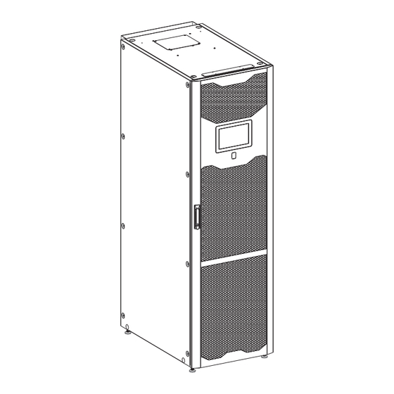
UPS P ARTS AND ODULES Display (MCU) Battery switch (SWBATT) Door with air filter Bypass Module (BM) Switch Lock Handle (locking system present on all modules) UPS status LED Power Module (PM) Battery Section (BU) Connectivity panel Cold Start section WARNING! The cabinet cannot be moved and/or delivered on site with Power Modules inserted. - Page 17 MCU WITH OPEN DOOR POWER MODULE 20kW (PM20) - Net weight 79.4 lb (36 Kg) POWER MODULE 34kW (PM36) - Net weight 81.6 lb (37 Kg) BYPASS MODULE (BM) - Net weight 37.5 lb (17 Kg) - 17 -...
-
Page 18: Connectivity Panel (Cp)
(CP) ONNECTIVITY ANEL (SMU) YSTEM ONITORING Communication Slot (SLOT 2) Signal AUX Contacts Slot (SLOT 1) NETMAN port R.E.P.O. Display port Signal input SMU status LEDs Signal output Switch Lock Service ports (PIB) ARALLEL NTERFACE OARD - 18 -... -
Page 19: Insertion/Extraction Modules And Units Procedure
INSERTION/EXTRACTION MODULES AND UNITS PROCEDURE (PM) OWER ODULE The following operations must only be performed by skilled and specifically trained personnel. When the PM is not inserted, uncovered parts with dangerous voltage are present within the corresponding backplane. Use Personal Protective Equipment (see "Important safety information" section). The PM, due to its weight, must be handled by at least two persons. -
Page 20: Extraction
XTRACTION Note: before extracting any PM, please ensure that the remaining PMs are capable of supporting the full load. To extract the PM from the cabinet, reverse the procedure described above. In brief: Switch off the PM using the display. Turn the Switch Lock 90°... -
Page 21: Insertion
NSERTION To insert the BM into the cabinet, use the following procedure: 1. Make sure that the System is in Service Bypass Mode, with: External Manual Bypass switch closed. External Input/Bypass switch opened. External Output switch opened. External Battery switch opened. 2. -
Page 22: Smu (System Monitoring Unit )
SMU (S YSTEM ONITORING The following operations must only be performed by skilled and specifically trained personnel. Use Personal Protective Equipment (see "Important safety information" section). When the SMU is not inserted, uncovered parts with dangerous voltage are present on the corresponding backplane. The SMU is pre-installed by the manufacturer. -
Page 23: Power Connection Information
OWER ONNECTION NFORMATION PM 20 MODULE Input AC Line Connection 3PH + N + PE (Single / Dual Mains) Size of line Terminal IN1, IN2, IN3, N / PE Wire IN1, IN2, IN3, N / PE Max admitted protection Power current neutral current Size... -
Page 24: Pm 34 Module
PM 34 MODULE Input AC Line Connection 3PH + N + PE (Single / Dual Mains) Size of line Terminal IN1, IN2, IN3, N / PE Wire IN1, IN2, IN3, N / PE Max admitted protection Power current neutral current module device (plant) Size... -
Page 25: System Protections Information
YSTEM ROTECTIONS NFORMATION THE INPUT, OUTPUT AND PROTECTIVE EARTHING CONDUCTORS MUST BE SIZED FOLLOWING THE RATED VOLTAGE AND CURRENT, AS SHOWN IN THE TABLES AND ALSO COMPLY WITH LOCAL AND NATIONAL REGULATION FOR MAXIMUM POWER RATING. THE PROTECTIVE EARTHING CONDUCTOR (PE) MUST BE CONNECTED PRIOR TO CONNECTING ANY WARNING INPUT / OUTPUT CABLES. -
Page 26: Removing Door
EMOVING DOOR Disconnect display cable Remove hinge pins - 26 -... -
Page 27: Replacing Door Air Filter
EPLACING DOOR AIR FILTER 1. Remove the locking nuts as shown in the figure below and store them. 2. Remove the air filter frames by lifting them up as shown in the following figure. 3. After replacing the filters, follow the above procedure in reverse to reassemble the frames. - 27 -... -
Page 28: Power Connection Detail
OWER ONNECTION ETAIL REMOVING REAR TERMINAL CONNECTION PROTECTION COVERS BEFORE REMOVING THEM, THE SYSTEM MUST BE COMPLETELY ISOLATED FROM ALL POWER SOURCES. Remove the terminal connection protection covers as shown in the figures below. - 28 -... - Page 29 - 29 -...
- Page 30 ATTENTION: CONNECT THE WIRES IN THE CORRECT POSITION. Wrong connections can cause damage to the UPS or the loads. Do not reverse the polarity of the batteries. Refer to the operative procedures section within the User manual. WARNING! This UPS does not need battery central point. Only connect + and – battery terminals to the relative bars.
-
Page 31: Top And Bottom Cable Entry
OP AND OTTOM CABLE ENTRY Drill holes for the cables in the top aluminum cover (for the top cable entry) or in the bottom aluminum cover (for the bottom cable entry). See figures below. To comply with IP20 protection degree, make sure that the holes size is slightly larger than the wires diameter. Insert conduits (if applicable) or ensure that any sharp edges, which could possibility damage cables, have been removed. - Page 32 TOP CABLE ENTRY BOTTOM CABLE ENTRY - 32 -...
-
Page 33: Jumper Removal For Dual Input
UMPER REMOVAL FOR NPUT XTERNAL Insulated input to synchronize the output of the UPS to an external source. To enable the external sync, refer to related manual. Input parameters: Phase – Neutral max. 120 Vac ± 10% Connection wires: 1.5 mm double insulation - 33 -... -
Page 34: Power Connection Positions
OWER ONNECTION OSITIONS - 34 -... -
Page 35: Earth Connection Position
ARTH CONNECTION POSITION - 35 -... -
Page 36: Communication Interface - Smu
COMMUNICATION INTERFACE - SMU R.E.P.O. This isolated input is used to turn the UPS off remotely in case of an emergency. The UPS is supplied from the factory with two “Remote Emergency Power Off” (R.E.P.O.) inputs terminals short-circuited. If R.E.P.O. is to be installed, remove the pre-installed short- circuit and connect to the normally closed contact of the stop device using a double insulated cable (1 - 1.5 mm with crimp terminal). -
Page 37: Auxiliary Signals
UXILIARY SIGNALS Insulated auxiliary signals: EXTERNAL TEMPERATURE PROBE Input to connect the external probe to measure the battery temperature. Please refer to the optional kit. EXTERNAL BATTERY BREAKER Output (default N.O.) for controlling the external battery breaker trip. The contact closes upon pressing the remote EPO or in the event of other fault conditions.
Need help?
Do you have a question about the M2U NP Series and is the answer not in the manual?
Questions and answers