Table of Contents
Advertisement
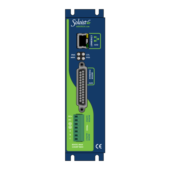
Quick Links
Advertisement
Table of Contents

Related Manuals for Aerotech Soloist MP Series


Summary of Contents for Aerotech Soloist MP Series
-
Page 1: Soloist Mp Hardware Manual
Soloist MP Hardware Manual Revision: 4.10.00... - Page 2 This manual contains proprietary information and may not be reproduced, disclosed, or used in whole or in part without the express written permission of Aerotech, Inc. Product names mentioned herein are used for identification purposes only and may be trademarks of their respective companies.
-
Page 3: Table Of Contents
2.4. Emergency Stop Sense Input (TB104) 2.4.1. Typical ESTOP Interface 2.5. RS-232 Interface (TB105) 2.6. PC Configuration and Operation Information Chapter 3: -I/O Expansion Board 3.1. User Power (TB201) 3.2. Brake Relay Connector (TB201) 3.3. Analog I/O Connector (TB202) 3.3.1. Analog Output 1 (TB202) www.aerotech.com... - Page 4 3.6. Auxiliary Encoder Channel / PSO Output (J201) 3.6.1. Position Synchronized Output (PSO)/Laser Firing (J201) Chapter 4: Standard Interconnection Cables 4.1. Joystick Interface 4.2. Handwheel Interface Chapter 5: Maintenance 5.1. Control Board 5.2. Preventative Maintenance Appendix A: Warranty and Field Service Appendix B: Revision History Index www.aerotech.com...
-
Page 5: List Of Figures
Digital Inputs Connected to a Current Sinking Device Figure 3-12: Auxiliary Encoder Channel (J201) Figure 3-13: PSO Interface Figure 4-1: Single Axis Joystick Interface Figure 4-2: Two Axis Joystick Interface Figure 4-3: Handwheel Interconnection (to Aux I/O) Figure 5-1: Control Board Assembly www.aerotech.com... - Page 6 Soloist MP Table of Contents This page intentionally left blank. www.aerotech.com...
-
Page 7: List Of Tables
Motor Power Output Connections (TB102) Table 2-9: Mating Connector Part Numbers for the Motor Power Output Connector Table 2-10: Wire Colors for Aerotech Supplied Cables (Brushless) Table 2-11: Wire Colors for Aerotech Supplied Cables (DC Brush) Table 2-12: Wire Colors for Aerotech Supplied Cables (Stepper) ... - Page 8 Mating Connector Part Numbers for the Auxiliary Encoder Connector (J201) Table 3-20: PSO Specifications Table 3-21: PSO Output Pins on the Auxiliary Encoder Connector (J201) Table 4-1: Standard Interconnection Cables Table 4-2: Joystick Cable Part Numbers Table 5-1: Control Board Fuse Information Table 5-2: LED Description Table 5-3: Preventative Maintenance www.aerotech.com...
-
Page 9: Eu Declaration Of Conformity
Declaration of Conformity Soloist MP EU Declaration of Conformity Manufacturer Aerotech, Inc. Address 101 Zeta Drive Pittsburgh, PA 15238-2811 Product Soloist MP Model/Types This is to certify that the aforementioned product is in accordance with the applicable requirements of the... -
Page 10: Agency Approvals
Soloist MP Declaration of Conformity Agency Approvals Aerotech, Inc. Model Soloist MP Series Digital Drives have been tested and found to be in accordance to the following listed Agency Approvals: Approval / Certification: CUS NRTL Approving Agency: TUV SUD America Inc. -
Page 11: Safety Procedures And Warnings
N O T E : Aerotech continually improves its product offerings; listed options may be superseded at any time. All drawings and illustrations are for reference only and were complete and accurate as of this manual’s release. - Page 12 4. Do not expose this product to environments or conditions outside of the listed specifications. Exceeding environmental or operating specifications can cause damage to the equipment. 5. Operators must be trained before operating this equipment. 6. All service and maintenance must be performed by qualified personnel. www.aerotech.com...
-
Page 13: Quick Installation Guide
Section 2.2. Motor Output Connections Motor Feedback Section 2.3. Motor Feedback Connections (J103) Ethernet / USB No Section / Standard Connection Control Supply Section 2.1.1. Control Supply Connections (TB103) Motor Supply Section 2.1.2. Motor Supply Connections (TB102) Additional I/O User / Application dependent www.aerotech.com... - Page 14 Soloist MP Quick Installation Guide This page intentionally left blank. www.aerotech.com...
-
Page 15: Chapter 1: Introduction
Soloist MP Chapter 1: Introduction Aerotech’s Soloist MP (Ultra-Compact "Micro" PWM) network digital drive is a high performance amplifier. The drive provides deterministic behavior, auto-identification, and easy software setup. The Soloist MP’s high performance double precision floating point DSP controls the digital PID and current loops. All system configuration is done using software-settable parameters, including control loop gains and system safety functions. -
Page 16: Table 1-1: Feature Summary
Refer to the Help file. Locked drive; firmware and calibration data on the drive cannot be modified by the -LCK user; the drive must be returned if updates are required; read/write access to parameters and programs is supported Chapter 1 www.aerotech.com... -
Page 17: Table 1-3: Ml Power Supply Options
Axis 3 brake -BRAKE-4 Axis 4 brake Table 1-4: Accessories Accessories Industrial Joystick (NEMA12 (IP54) rated); refer to Section 4.1. BRAKE24-2 24 VDC, 2 A power supply for optional brake Joystick/Handwheel Refer to Section 4.1. Section 4.2. www.aerotech.com Chapter 1... -
Page 18: Figure 1-2: Functional Diagram
Soloist MP Introduction The following block diagram shows a connection summary. For detailed connection information, refer to Chapter 2 and Chapter 3. Figure 1-2: Functional Diagram Chapter 1 www.aerotech.com... -
Page 19: Drive And Software Compatibility
Drives that list a specific version number in the Last Software Version column will not be supported after the listed version. Table 1-5: Drive and Software Compatibility Drive Type Firmware Revision First Software Version Last Software Version 2.01 Current 2.55 Current www.aerotech.com Chapter 1... -
Page 20: Electrical Specifications
Power stage bias supply under voltage Optical and transformer isolation between control and power Isolation stages. 1. AC input voltage and load dependent. 2. Dependent on total output power: efficiency increases with increasing output power. Chapter 1 www.aerotech.com... -
Page 21: System Power Requirements
Ploss = 3 * I(rms)^2 * R(line-line)/2 Pin = SUM ( Pout + Ploss ) / EfficiencyFactor DC Brush Motor Pout [W] = Torque [N·m] * Angular velocity[rad/sec] Ploss = I(rms)^2 * R Pin = SUM ( Pout + Ploss ) / EfficiencyFactor www.aerotech.com Chapter 1... -
Page 22: Power Dissipation
Figure 1-3: Power Dissipation vs. Output Current Figure 1-4: Ambient Temperature vs. Power Dissipation EXAMPLE: 80 VDC Bus operation at 2.4 A Power Dissipation = 7.5 Watts Maximum Ambient Temperature = 53°C Chapter 1 www.aerotech.com... -
Page 23: Mechanical Design
25 mm (1") of free air space. A space of 100 mm (4") should be allowed along the front of the unit for cable connections. Figure 1-5: Dimensions Table 1-7: Physical Specifications Weight Standard 0.454 kg (1.0 lb) w/ -IO option 0.544 kg (1.2 lb) w/ -MXU option 0.544 kg (1.2 lb) www.aerotech.com Chapter 1... -
Page 24: Environmental Specifications
Maximum relative humidity is 80% for temperatures up to 31°C. Decreasing Humidity linearly to 50% relative humidity at 40°C. Non condensing. Altitude Up to 2000 meters. Pollution Pollution degree 2 (normally only non-conductive pollution). Indoor use only. Chapter 1 www.aerotech.com... -
Page 25: Chapter 2: Installation And Configuration
D A N G E R : Soloist MP and PS-MP systems must be installed inside a rack or enclosure to restrict access while energized. D A N G E R : To minimize the possibility of bodily injury or death, disconnect all electrical power prior to performing any maintenance or making adjustments to the equipment. www.aerotech.com Chapter 2... -
Page 26: Control Supply Connections (Tb103)
(2) Refer to local electrical safety requirements to correctly size external system wires. Table 2-2: Mating Connector Part Numbers for the Control Supply Connector (TB103) Tightening Wire Size: Description Aerotech P/N Phoenix P/N Torque (Nm) AWG [mm 3-Pin Terminal Block ECK01387 1803581 0.22 - 0.25... -
Page 27: Motor Supply Connections (Tb102)
(2) Refer to local electrical safety requirements to correctly size external system wires. Table 2-4: Mating Connector Part Numbers for the Motor Supply Connector (TB102) Tightening Wire Size: Description Aerotech P/N Phoenix P/N Torque (Nm) [AWG] 7-Pin Terminal Block ECK01389 1803620 0.22 - 0.25... -
Page 28: External Power Supply Options
1.3 mm (#16 AWG) 300 V wire AC Power 1.3 mm (#16 AWG) 300 V wire Protective Ground (required for safety) 1.3 mm (#16 AWG) 300 V wire User must provide 10 A, 250 VAC fuse(s) or circuit breaker(s) to protect AC inputs Chapter 2 www.aerotech.com... -
Page 29: Figure 2-3: Control And Motor Power Wiring Using A Tm3 Transformer
Installation and Configuration Soloist MP Figure 2-3: Control and Motor Power Wiring using a TM3 Transformer www.aerotech.com Chapter 2... -
Page 30: Figure 2-4: Ps-Mp Option (2 Axis, 120 W, 48 Vdc Output, With Brake)
Soloist MP Installation and Configuration Figure 2-4: PS-MP Option (2 Axis, 120 W, 48 VDC Output, with Brake) Figure 2-5: PS-MP Option (2 Axis, 240 W, 48 VDC Output, with Brake) Chapter 2 www.aerotech.com... -
Page 31: Figure 2-6: Ps-Mp Option (4 Axis, 480 W, 48 Vdc Output, With Brake)
Installation and Configuration Soloist MP Figure 2-6: PS-MP Option (4 Axis, 480 W, 48 VDC Output, with Brake) www.aerotech.com Chapter 2... -
Page 32: Minimizing Conducted, Radiated, And System Noise
EMC testing must be conducted on the final product configuration. Ferrite beads can be used on the motor leads to reduce the effects of PWM noise. Table 2-7: Ferrite Noise Suppression Part Numbers Wire Size Aerotech P/N Third Party P/N 13.3 mm (#6 AWG) #2643626502 Elna Fair-Rite Products 8.3 mm... -
Page 33: Motor Output Connections
(#20 AWG) Earth Ground to Motor (required for safety) Table 2-9: Mating Connector Part Numbers for the Motor Power Output Connector Tightening Wire Size: Description Aerotech P/N Phoenix P/N Torque (Nm) [AWG] 7-Pin Terminal Block ECK01389 1803620 0.22 - 0.25 2.0 - 0.516 [14-30]... -
Page 34: Brushless Motor Connections
(2) “&” (Red & Orange) indicates two wires; “ / ” (Green/White) indicates a single wire Brushless motors are commutated electronically by the controller, typically using Hall-effect devices. If you are using standard Aerotech motors and cables, motor phasing adjustments are not required and this section may be skipped. -
Page 35: Powered Motor Phasing
Installation and Configuration Soloist MP 2.2.1.1. Powered Motor Phasing Refer to the Motor Phasing Calculator in the Configuration Manager for motor, Hall, and encoder phasing. Figure 2-8: Encoder and Hall Signal Diagnostics www.aerotech.com Chapter 2... -
Page 36: Unpowered Motor And Feedback Phasing
With the designations of the motor and Hall leads of a third party motor determined, the motor can now be connected to an Aerotech system. Connect motor lead A to motor connector A, motor lead B to motor connector B, and motor lead C to motor connector C. Hall leads should also be connected to their respective feedback connector pins (Hall A lead to the Hall A feedback pin, Hall B to Hall B, and Hall C to Hall C). -
Page 37: Dc Brush Motor Connections
Red & Orange Yellow & Blue Black Yellow & Blue (1) Wire Color Set #1 is the typical Aerotech wire set used by Aerotech. (2) “&” (Red & Orange) indicates two wires; “ / ” (Green/White) indicates a single wire www.aerotech.com Chapter 2... -
Page 38: Dc Brush Motor Phasing
5. Connect the motor lead from the voltmeter to the ØA motor terminal on the Soloist MP. Connect the motor lead from the negative lead of the voltmeter to the ØC motor terminal on the Soloist MP. N O T E : If using standard Aerotech motors and cables, motor and encoder connection adjustments are not required. -
Page 39: Stepper Motor Connections
Green/Yellow & Shield Black Brown Yellow White White & Red (1) Wire Color Set #1 is the typical Aerotech wire set used by Aerotech. (2) “&” (Red & Orange) indicates two wires; “ / ” (Green/White) indicates a single wire www.aerotech.com Chapter 2... -
Page 40: Stepper Motor Phasing
Installation and Configuration 2.2.3.1. Stepper Motor Phasing N O T E : If using standard Aerotech motors and cables, motor and encoder connection adjustments are not required. A stepper motor can be run with or without an encoder. If an encoder is not being used, phasing is not necessary. -
Page 41: Motor Feedback Connections (J103)
Input Counterclockwise End of Travel Limit Input Brake Output + Output Table 2-14: Mating Connector Part Numbers for the Motor Feedback Connector (J103) Mating Connector Aerotech P/N Third Party P/N 25-Pin D-Connector ECK00101 FCI DB25P064TXLF Backshell ECK00656 Amphenol 17E-1726-2 www.aerotech.com... -
Page 42: Encoder Interface (J103)
+5V Power for Encoder (500 mA max) Output Encoder Marker Reference Pulse - Input Encoder Marker Reference Pulse + Input Encoder Cosine + Input Encoder Cosine - Input Encoder Sine + Input Encoder Sine - Input Signal Common for Encoder Chapter 2 www.aerotech.com... -
Page 43: Rs-422 Line Driver Encoder (Standard)
An analog encoder is used with the -MXU option (refer to Section 2.3.1.2. for more information). Table 2-16: Encoder Specifications Specification Value Encoder Frequency 10 MHz maximum (25 nsec minimum edge separation) x4 Quadrature Decoding 40 million counts/sec Figure 2-15: Line Driver Encoder Interface (J103) www.aerotech.com Chapter 2... -
Page 44: Analog Encoder Interface
Analog Encoder Phasing Reference Diagram N O T E : The input amplitude is measured peak to peak for any encoder signal (sin, sin-n, cos, cos-n) relative to signal common. These signals have a typical offset voltage of 2V to 2.5V. Chapter 2 www.aerotech.com... -
Page 45: Figure 2-17: Analog Encoder Interface (J103)
Installation and Configuration Soloist MP Figure 2-17: Analog Encoder Interface (J103) www.aerotech.com Chapter 2... -
Page 46: Encoder Phasing
Figure 2-18: Encoder Phasing Reference Diagram (Standard) N O T E : Encoder manufacturers may refer to the encoder signals as A, B, and Z. The proper phase rela- tionship between signals is shown in Figure 2-18. Chapter 2 www.aerotech.com... -
Page 47: Figure 2-19: Position Feedback In The Diagnostic Display
Installation and Configuration Soloist MP Figure 2-19: Position Feedback in the Diagnostic Display www.aerotech.com Chapter 2... -
Page 48: Hall-Effect Interface (J103)
+5V Power for Encoder (500 mA max) Output Hall-Effect Sensor B (brushless motors only) Input Hall-Effect Sensor A (brushless motors only) Input Hall-Effect Sensor C (brushless motors only) Input Signal Common for Encoder Figure 2-20: Hall-Effect Inputs (J103) Chapter 2 www.aerotech.com... -
Page 49: Thermistor Interface (J103)
The nominal trip value of the sensor is 1k Ohm. Table 2-19: Thermistor Interface Pin on the Motor Feedback Connector (J103) Pin# Description In/Out/Bi Motor Over Temperature Thermistor Input Figure 2-21: Thermistor Interface Input (J103) www.aerotech.com Chapter 2... -
Page 50: Encoder Fault Interface (J103)
Table 2-20: Encoder Fault Interface Pin on the Motor Feedback Connector (J103) Pin# Description In/Out/Bi Encoder Fault Input Input Figure 2-22: Encoder Fault Interface Input (J103) Chapter 2 www.aerotech.com... -
Page 51: End Of Travel Limit Input Interface (J103)
End of Travel Limit Input Pins on the Motor Feedback Connector (J103) Pin# Description In/Out/Bi Clockwise End of Travel Limit Input +5V Power for Limit Switches (500 mA max) Output Signal Common for Limit Switches Home Switch Input Input Counterclockwise End of Travel Limit Input www.aerotech.com Chapter 2... -
Page 52: Figure 2-24: End Of Travel Limit Interface Input (J103)
Soloist MP Installation and Configuration Figure 2-24: End of Travel Limit Interface Input (J103) Chapter 2 www.aerotech.com... -
Page 53: End Of Travel Limit Phasing
CW and CCW inputs at the motor feedback connector. The logic level of the EOT limit inputs may be viewed in the Diagnostic Display (shown in Figure 2-25). Figure 2-25: Limit Input Diagnostic Display www.aerotech.com Chapter 2... -
Page 54: Brake Output (J103)
Refer to Section 3.2. for more information on using the brake output with the solid-state relay. Table 2-22: Brake Output Pins on the Motor Feedback Connector (J103) Pin# Description In/Out/Bi Brake Output - Output Brake Output + Output Chapter 2 www.aerotech.com... -
Page 55: Analog Input 0 (J103)
Port 0 Analog Input Connector Pins on the Motor Feedback Connector (J103) Pin# Description In/Out/Bi Analog Input 0 - Input Analog Input 0 + Input Signal Common for Limit Switches Signal Common for Encoder Figure 2-26: Analog Input 0 (J103) www.aerotech.com Chapter 2... -
Page 56: Emergency Stop Sense Input (Tb104)
Table 2-25. These devices are applied across the switched coil to suppress transient voltages. Table 2-25: Electrical Noise Suppression Devices Device Aerotech P/N Third Party P/N RC (.1uf / 200 ohm) Network EIC00240 Electrocube RG1782-8 Varistor EID00160... -
Page 57: Typical Estop Interface
Figure 2-28: Typical Emergency Stop Circuit Table 2-27: Typical ESTOP Relay Ratings Axes Aerotech P/N Third Party P/N Up to 5 ECW01024 Sprecher & Schuh CA7-16C-M40-24D N O T E : Multiple contacts are used in series to achieve desired DC contact rating. -
Page 58: Rs-232 Interface (Tb105)
Output RS-232 Receive Bidirectional Signal Common Table 2-29: Mating Connector Part Numbers for the RS-232 Port Connector (TB105) Wire Size: Description Aerotech P/N Phoenix P/N AWG [mm 3-Pin Terminal Block ECK01449 1881338 0.5 - 0.080 [20-28] Figure 2-29: RS-232 Interface (TB105) Chapter 2 www.aerotech.com... -
Page 59: Pc Configuration And Operation Information
Installation and Configuration Soloist MP 2.6. PC Configuration and Operation Information For additional information about PC configuration, hardware requirements, programming, utilities, and system operation refer to the Soloist Help file. www.aerotech.com Chapter 2... - Page 60 Soloist MP Installation and Configuration This page intentionally left blank. Chapter 2 www.aerotech.com...
-
Page 61: Chapter 3: -I/O Expansion Board
The -IO option board is 8 digital opto-inputs, 8 digital opto-outputs, 1 analog input, 1 analog output, a second encoder channel, and a brake/relay output. D A N G E R : Always disconnect the Mains power connection before opening the Soloist MP chassis. Figure 3-1: Soloist MP with -IO Option Board www.aerotech.com Chapter 3... -
Page 62: User Power (Tb201)
A user accessible power supply (+5V at 0.5 A) is available between the TB201 pin 3 +5V terminal and TB201 pin 4 GND terminal. Table 3-1: User Common Connector Pins on the Brake Relay Connector (TB201) Pin# Description In/Out/Bi Internal +5 Volt Power Supply (0.5 A max) Output Signal Common Chapter 3 www.aerotech.com... -
Page 63: Brake Relay Connector (Tb201)
Brake Power Supply (+) Input Brake Power Supply (-) Input Table 3-4: Mating Connector Part Numbers for the Brake Relay Connector (TB201) Wire Size: AWG [mm Type Aerotech P/N Phoenix P/N 4-Pin Terminal Block ECK01293 1881341 20-28 [0.5- 0.080] www.aerotech.com Chapter 3... -
Page 64: Figure 3-2: Brake Connected To J103
24 VDC brake connected to TB201. The user must connect J103 pin 13 to J103 pin 25. In this case, J103 would function as an interlock to prevent the brake from releasing if the Motor Feedback connector is not connected. Figure 3-3: Brake Connected to TB201 Chapter 3 www.aerotech.com... -
Page 65: Analog I/O Connector (Tb202)
Inverting Analog Input 1 Input Analog Output 1 Output Table 3-6: Mating Connector Part Numbers for the Analog Output Connector Wire Size: AWG [mm Type Aerotech P/N Phoenix P/N 4-Pin Terminal Block ECK01293 1881341 20-28 [0.5- 0.080] www.aerotech.com Chapter 3... -
Page 66: Analog Output 1 (Tb202)
5 mA Resolution (bits) 16 bits Resolution (volts) 153 µV Table 3-8: Port 1 Analog Output Pins on the Analog I/O Connector (TB202) Pin# Description In/Out/Bi Analog Common Analog Output 1 Output Figure 3-4: Analog Output 1 Connector (TB202) Chapter 3 www.aerotech.com... -
Page 67: Differential Analog Input 1 (Tb202)
N O T E : Analog Input 0 is available on J103 (see Section 2.3.7.). Table 3-10: Differential Analog Input 1 Pins on the Analog I/O Connector (TB202) Pin# Description In/Out/Bi Analog Common Non-inverting Analog Input 1 Input Inverting Analog Input 1 Input Figure 3-5: Analog Input Typical Connection (TB202) www.aerotech.com Chapter 3... -
Page 68: Opto Out Connector (Digital Outputs) (Tb204)
Digital Output 7 (Optically-Isolated) Output Table 3-13: Mating Connector Part Numbers for the Opto Out Connector (TB204) Wire Size: mm [AWG] Aerotech P/N Phoenix P/N 10-Pin Terminal Block ECK01294 1881406 0.5-0.080 [20-28] Suppression diodes must be installed on outputs driving relays or other inductive devices. This protects the outputs from damage caused by inductive spikes. -
Page 69: Figure 3-6: Digital Opto-Isolated Outputs (-Io Board)
-IO Expansion Board Soloist MP Figure 3-6: Digital Opto-Isolated Outputs (-IO Board) www.aerotech.com Chapter 3... -
Page 70: Figure 3-7: Digital Outputs Connected In Current Sourcing Mode
Soloist MP -IO Expansion Board Figure 3-7: Digital Outputs Connected in Current Sourcing Mode Figure 3-8: Digital Outputs Connected in Current Sinking Mode Chapter 3 www.aerotech.com... -
Page 71: Opto In Connector (Digital Inputs) (Tb203)
Digital Input Common for inputs 4 - 7 Input Table 3-16: Mating Connector Part Numbers for the Opto In Connector (TB203) Wire Size: mm [AWG] Aerotech P/N Phoenix P/N 10-Pin Terminal Block ECK01294 1881406 0.5-0.080 [20-28] N O T E : Inputs must be connected in the all sourcing or all sinking configuration. -
Page 72: Figure 3-9: Digital Opto-Isolated Inputs
Soloist MP -IO Expansion Board Figure 3-9: Digital Opto-Isolated Inputs Chapter 3 www.aerotech.com... -
Page 73: Figure 3-10: Digital Inputs Connected To A Current Sourcing Device
-IO Expansion Board Soloist MP Figure 3-10: Digital Inputs Connected to a Current Sourcing Device Figure 3-11: Digital Inputs Connected to a Current Sinking Device www.aerotech.com Chapter 3... -
Page 74: Auxiliary Encoder Channel / Pso Output (J201)
Auxiliary RS-422 Encoder Sine - Bidirectional (1) For PSO, see Section 3.6.1. Table 3-19: Mating Connector Part Numbers for the Auxiliary Encoder Connector (J201) J201 Adapter Cable Assembly Aerotech P.N. Third Party P.N. 9 Pin Standard D-style C20931 25 Pin Standard D-style C20932 Flying Leads... -
Page 75: Figure 3-12: Auxiliary Encoder Channel (J201)
-IO Expansion Board Soloist MP Figure 3-12: Auxiliary Encoder Channel (J201) www.aerotech.com Chapter 3... -
Page 76: Position Synchronized Output (Pso)/Laser Firing (J201)
Table 3-21: PSO Output Pins on the Auxiliary Encoder Connector (J201) Pin# Description In/Out/Bi Auxiliary RS-422 Marker Pulse - / PSO Output Bidirectional Auxiliary RS-422 Marker Pulse +/ PSO Output Bidirectional Encoder Power Common Chapter 3 www.aerotech.com... -
Page 77: Figure 3-13: Pso Interface
-IO Expansion Board Soloist MP Figure 3-13: PSO Interface www.aerotech.com Chapter 3... - Page 78 Soloist MP -IO Expansion Board This page intentionally left blank. Chapter 3 www.aerotech.com...
-
Page 79: Chapter 4: Standard Interconnection Cables
Accessories Soloist MP Chapter 4: Standard Interconnection Cables N O T E : A complete list of Aerotech cables can be found on the website at http://www.aerotechmotioncontrol.com/manuals/index.aspx. Table 4-1: Standard Interconnection Cables Cable Part # Description Joystick Section 4.1. ECZ01231 BBA32 Interconnect Cable www.aerotech.com... -
Page 80: Joystick Interface
Accessories 4.1. Joystick Interface Aerotech joysticks JI (NEMA12 (IP54) rated) and JBV are powered from 5V and have a nominal 2.5V output in the center detent position. Three buttons are used to select axis pairs and speed ranges. An optional interlock signal is used to indicate to the controller that the joystick is present. -
Page 81: Figure 4-2: Two Axis Joystick Interface
Accessories Soloist MP Figure 4-2: Two Axis Joystick Interface www.aerotech.com Chapter 4... -
Page 82: Handwheel Interface
Accessories 4.2. Handwheel Interface A handwheel (such as the Aerotech HW-xxx-xx) can be used to manually control axis position. The handwheel must provide 5V differential quadrature signals to the Soloist MP. A handwheel can be connected to the Aux I/O as shown in Figure 4-3. -
Page 83: Chapter 5: Maintenance
D A N G E R : Before performing any tests, be aware of lethal voltages inside the controller and at the input and output power connections. A qualified service technician or electrician should perform these tests. www.aerotech.com Chapter 5... -
Page 84: Control Board
Maintenance 5.1. Control Board Figure 5-1: Control Board Assembly Table 5-1: Control Board Fuse Information Fuse Description Size Aerotech P/N Manufacturer's P/N Control Power at TB103-1 2 A F.B. EIF00136 Littelfuse 251002 5 A S.B. Bus Power at TB102-1 EIF01026 Littelfuse 3721500041 (5 mm) Note: F1 is soldered to the circuit board. -
Page 85: Preventative Maintenance
The electrical power must be disconnected from the Soloist MP while cleaning. Do not allow cleaning substances or other fluids to enter the Soloist MP or to get on to any of the connectors. Avoid cleaning labels to prevent removing the label information. www.aerotech.com Chapter 5... - Page 86 Soloist MP Maintenance This page intentionally left blank. Chapter 5 www.aerotech.com...
-
Page 87: Appendix A: Warranty And Field Service
Aerotech makes no warranty that its products are fit for the use or purpose to which they may be put by the buyer, whether or not such use or purpose has been disclosed to Aerotech in specifications or drawings previously or subsequently provided, or whether or not Aerotech’s... - Page 88 Aerotech's approval. On-site Warranty Repair If an Aerotech product cannot be made functional by telephone assistance or by sending and having the customer install replacement parts, and cannot be returned to the Aerotech service center for repair, and if Aerotech determines the problem could be warranty-related, then the following policy applies:...
-
Page 89: Appendix B: Revision History
Section 3.4. Opto Out Connector (Digital Outputs) (TB204) Section 3.6.1. Position Synchronized Output (PSO)/Laser Firing (J201) Section 5.1. Control Board 4.08.00 4.07.00 4.06.00 4.05.00 Revision changes have been archived. If you need a copy of this revision, contact Aerotech 4.04.00 Global Technical Support. 4.03.00 4.02.00 4.01.00 4.00.00 www.aerotech.com... - Page 90 Soloist MP Revision History This page intentionally left blank. Appendix B www.aerotech.com...
-
Page 91: Index
Digital Outputs Digital Outputs (-IO Board) Brake Connected to J207 dimensions Brake Connected to TB20 Din Rail Clip Mounting Hardware Brake Output Drive and Software Compatibility Brake Output Connector Pin Assignment Brake Output Pin Assignment Efficiency of Power Amplifier specifications www.aerotech.com... - Page 92 Din Rail Clip Handwheel Interface Humidity optional joysticks Options 16-17 Inputs Connected to a Current Sinking Device Output Specifications Inputs Connected to a Current Sourcing Device 73 Output Voltage specifications inspect all cables and connections Outputs Connected in Current Sinking Mode www.aerotech.com...
- Page 93 User Power Supply specifications RS-232 Port Connector Mating Connector RS-422 Line Driver Encoder (Standard) Wire Colors for Supplied Cables 34,37,39 Screws Din Rail Clip Single Axis Joystick Interface solid state brake control relay Standard Features Stepper Motor Connections Stepper Motor Phasing Support www.aerotech.com...
- Page 94 Soloist MP Index This page intentionally left blank. www.aerotech.com...
Need help?
Do you have a question about the Soloist MP Series and is the answer not in the manual?
Questions and answers