Advertisement
Quick Links
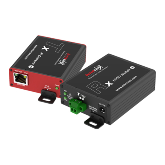
ETP-101T/R 설치 가이드 / Installation Guide
구성품 / Package Contents
브라켓
Terminal 커넥터
ETP-101T / 101R
Terminal connect
Bracket
제품 각 부분의 명칭 / Hardware Overview
Data Rate 스위치
Data Rate Switch
Left
ACT
Data Rate
Attention
10M
100M
Polarity
LINK
Bracket
상태 표시등
Status LED indicator
Terminal 커넥터
브라켓 홀
Terminal connector
Bracket Hole
LINK/ACT
PoE
Tx_Right
PoE
ON
Ethernet
Bracket
PoE 스위치
브라켓 홀
RJ45
PoE Switch
Bracket Hole
LINK/ACT
PoE
Rx_Right
Ethernet
Bracket
RJ45
브라켓 홀
Bracket Hole
제품 설치 가이드
1. 별도의 IP설정이 필요없이 자동으로 카메라에 IP를 부여하는 경우(DHCP 등)를
제외하고, 카메라 제조사 설명서를 참조하여 카메라에 IP주소를 설정해 둡니다.
2. ETP-101T(송신기)와 ETP-101R(수신기)의 Data Rate(10M/100M)를 동일하게
맞춥니다.
3. 카메라에 전원을 공급하기위해 ETP-101T(송신기)의 PoE 스위치를 ON 위치로
합니다.
설치 가이드
Installation Guide
* 카메라 대신 PC와 같은 장치를 사용할 경우, PoE 스위치를 OFF 위치로 합니다.
4. 2-Wire 케이블을 Terminal 커넥터로 ETP-101T(송신기) 와 ETP-101R(수신기)에
각각 연결합니다.
*
,
극성에 주의하여 연결 바랍니다. 반대로 연결하면 동작이 안됩니다.
5. 56V 전원 어댑터를 ETP-101R(수신기)에 먼저 연결한 후 AC전원 콘센트에
연결합니다.
* 케이블의 종류 및 상태, PoE 카메라의 소비전력(W) 등에 따라 실제 연결 가능한
총 거리가 줄어들 수 있습니다.
56V DC
6. ETP 제품이 문제 없이 연결된 경우, PWR/Terminal LINK LED가 켜진 것을
확인합니다.
7. 동봉된 브라켓을 ETP-101T(송신기) /101R(수신기)에 부착한 후 전체 제품이
움직이지 않도록 잘 고정시킵니다.
8. 준비된 UTP케이블(랜선)을 이용하여 작동중인 NVR과 ETP-101R(수신기)을 먼저
DC 전원 어댑터
연결하고, 이후 카메라와 ETP-101T(송신기)를 연결합니다.
DC Power Jack
9. Ethernet 인터페이스의 ACT / LINK LED 및 Terminal 인터페이스의 ACT LED가
깜박임을 확인합니다.
* ETP-101T(송신기)/101R (수신기)두 제품은 Terminal 커넥터를 통해 데이터와
전원을 함께 전송합니다. ETP-101R(수신기)은 어댑터 및 PoE 스위치
장치(PoE+PD 적용)를 통해 전원을 공급 받을 수 있습니다. 단, 안정적인 카메라
동작을 위해 56VDC 어댑터 사용을 권장합니다. (PoE 스위치 장치와 어댑터를
PWR
동시에 사용하여 전원 공급 시 어댑터 전원을 우선적으로 사용하여 전원이 공급됩니다.)
OFF
* 노트북 컴퓨터 등을 NVR쪽 ETP-101R(수신기)에 연결하여 전 구간의 통신 상태를
확인하기 위한 Ping 테스트를 권장합니다.
10. NVR에 연결된 모니터를 통해 각 카메라의 영상이 잘 나오는 지 확인합니다
상태 표시등 정보
전원 LED
Power LED
표시
색상
PWR
PWR
LINK
ACT
LINK / ACT
PoE
기능
56V DC 연결됨
Terminal 포트를 통해 ETP 제품들이 연결됨
데이터 전송 시 깜빡임 [Terminal 라인]
데이터 전송 시 깜빡임[Ethernet 라인]
PoE 전원 공급 상태 / 2-Wire 전원 공급 상태
Product I nstallation Guide
1. Other than automatic IP setting (i.e. DHCP), set the IP address on the camera
following the camera manufacturer's manual.
2. Set the Data Rate (10M / 100M) of the ETP-101T (transmitter) and the
ETP-101R (receiver) to the same.
3. Set ON the PoE switch of ETP-101T (transmitter) to supply power to the
camera.
* IF use a device such as a PC instead of a camera, set the PoE switch to
the OFF position.
4. Connect Terminal connectors of 2-Wire cable to each ETP-101T(Tx) and
ETP-101R(Rx).
* Be sure to connect polarity(
,
) carefully. If the connection is reversed,
it will not work.
5. Connect 56V DC power to ETP-101R(Rx) first and then to AC outlet.
* The total distance may vary with the type and condition of cables, and
power consumption of PoE camera.
6. When they are connected without any problem, PWR and Terminal LINK LED
are on.
7. Adhere the brackets in the package to ETP-101T(Tx)/ETP-101R(Rx) and
then fix up the products.
8. Connect the UTP(LAN) cable between ETP-101R(Rx)and NVR first and then
between ETP-101T(Tx) and camera.
9. Make sure that the ACT/LINK LED on ethernet interface and ACT LED on
Terminal interface are on and flickering.
* Both ETP-101T(Tx) and ETP-101R(Rx)send data and power together via
Terminal connector and ETP-101R(Rx)can be powered by PoE Switch
Device (PoE+ PD Supported) but for safe working, it recommeded to use
56VDC Power supply on ETP-101R.(when using both PoE switch Device
and power supply at the same time, power supply works preferentially.)
* Ping test is recommended to confirm the whole network.
LED Indicators
Indicator
Color
Function
PWR
56V DC Link
LINK
ETP-Product Link
ACT
Data Act [Terminal Line]
LINK / ACT
Data Act [Ethernet Line]
PoE
PoE Output On / Power over 2-Wire Cable On
Advertisement

Related Manuals for Intercoax ETP-101T


Summary of Contents for Intercoax ETP-101T
- Page 1 제외하고, 카메라 제조사 설명서를 참조하여 카메라에 IP주소를 설정해 둡니다. following the camera manufacturer’s manual. 2. ETP-101T(송신기)와 ETP-101R(수신기)의 Data Rate(10M/100M)를 동일하게 2. Set the Data Rate (10M / 100M) of the ETP-101T (transmitter) and the 맞춥니다. ETP-101R (receiver) to the same.
- Page 2 Warranty Use only rated 56V power adapter specified by the manufacturer. * Connect DC power to ETP-101T/R first and then to AC outlet. 본 제품은 자사의 철저한 품질 관리와 정밀 검사에 합격한 제품입니다. This device has passed the quality control and product inspection.
Need help?
Do you have a question about the ETP-101T and is the answer not in the manual?
Questions and answers