Advertisement
DESCRIPTION
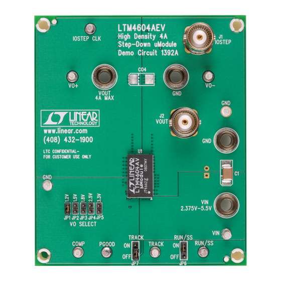
Demonstration circuit 1392A features the LTM
the high efficiency, high density switch mode step-down
μModule
®
regulator. The input voltage range is from 2.375V
to 5.5V with a jumper selectable output voltage from 0.8V
to 3.3V. The rated load current is 4A, while derating is
necessary for certain V
By using the TRACK pin, the output can be set to coin-
cidentally or ratiometrically track to another voltage rail.
PERFORMANCE SUMMARY
PARAMETER
Input Voltage Range
Output Voltage, V
OUT
Maximum Continuous Output Current
Default Operating Frequency
Efficiency
BOARD PHOTO
Arrow.com.
Downloaded from
®
4604AEV,
, V
and thermal conditions.
IN
OUT
(T
A
CONDITION
Jumper Selectable (Open for 0.8V)
Derating is Necessary for Certain V
Thermal Conditions
V
= 5V, V
IN
OUT
DEMO MANUAL DC1392A
2.375V
IN(MIN)
µModule Regulator
The LTM4604A data sheet must be read in conjunction
with this demo manual prior to working on or modifying
demo circuit DC1392A.
Design files for this circuit board are available at
http://www.linear.com/demo
L, LT, LTC, LTM, μModule, Linear Technology and the Linear logo are registered trademarks of
Linear Technology Corporation. All other trademarks are the property of their respective owners.
= 25°C)
, V
and
IN
OUT
= 3.3V, I
= 4A
OUT
LTM4604A
, 4A Step-Down
VALUE
2.375V to 5.5V
1.2V, 1.5V, 1.8V, 2.5V, 3.3V; ±2%
4A DC
1.25MHz
88% Typical, See Figure 3
dc1392af
1
Advertisement
Table of Contents

Related Manuals for Linear Technology DC1392A


Summary of Contents for Linear Technology DC1392A
- Page 1 V and thermal conditions. L, LT, LTC, LTM, μModule, Linear Technology and the Linear logo are registered trademarks of By using the TRACK pin, the output can be set to coin- Linear Technology Corporation. All other trademarks are the property of their respective owners.
- Page 2 LTM4604A. (10mV/A), the output voltage can be monitored at BNC connector J2. 3. Turn on the power at the input. The output voltage should be 1.2V ±2%. Figure 1. Test Setup of DC1392A dc1392af Arrow.com. Arrow.com. Downloaded from Downloaded from...
- Page 3 DEMO MANUAL DC1392A QUICK START PROCEDURE INPUT OR OUTPUT CAPACITOR Figure 2. Scope Probe Placements for Measuring Input or Output Ripple Figure 3. Measured Supply Efficiency with Different V and V dc1392af Arrow.com. Arrow.com. Arrow.com. Downloaded from Downloaded from Downloaded from...
- Page 4 DEMO MANUAL DC1392A PARTS LIST ITEM REFERENCE PART DESCRIPTION MANUFACTURER/PART NUMBER Required Circuit Components C1, CO5 CAP ., X5R, 100μF , 6.3V, 20%, 1812 TDK, C4532X5R0J107M CIN1, CIN2 CAP ., X5R, 10μF , 6.3V, 10%, 1206 AVX, 12066D106KAT2A CAP ., X5R, 22μF , 6.3V, 10%, 1206 AVX, 12066D226KAT2A RES., CHIP , 10k, 1/16W, 1%, 0603...
- Page 5 Information furnished by Linear Technology Corporation is believed to be accurate and reliable. However, no responsibility is assumed for its use. Linear Technology Corporation makes no representa- tion that the interconnection of its circuits as described herein will not infringe on existing patent rights.
- Page 6 Linear Technology Corporation (LTC) provides the enclosed product(s) under the following AS IS conditions: This demonstration board (DEMO BOARD) kit being sold or provided by Linear Technology is intended for use for ENGINEERING DEVELOPMENT OR EVALUATION PURPOSES ONLY and is not provided by LTC for commercial use. As such, the DEMO BOARD herein may not be complete in terms of required design-, marketing-, and/or manufacturing-related protective considerations, including but not limited to product safety measures typically found in finished commercial goods.
Need help?
Do you have a question about the DC1392A and is the answer not in the manual?
Questions and answers