Linear Technology DC1317A-B Quick Start Manual
Active reset isolated 18-72v input to 5v @25a dc/dc power converter
Hide thumbs
Also See for DC1317A-B:
- Quick start manual (8 pages) ,
- Quick start manual (9 pages) ,
- Quick start manual (9 pages)
Advertisement
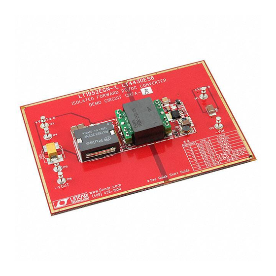
QUICK START GUIDE FOR DEMONSTRATION CIRCUIT 1317A-B
ACTIVE RESET ISOLATED 18-72V INPUT TO 5V @25A DC/DC POWER CONVERTER
DESCRIPTION
DESCRIPTION
DESCRIPTION
DESCRIPTION
Demonstration circuit 1317A-B is isolated input to
high current output 1/8th Brick footprint
featuring the LT ® 1952 switching controller with Ac-
tive Reset circuit. The Active Reset circuit can im-
prove the efficiency in wide input voltage applica-
tions. Also, the Active Reset allows the implementa-
tion of self-driven synchronous secondary rectifiers
in some applications.
The DC1317A-B converts isolated wide 18V to 72V
input to 5V output and provides over 30A of output
current depending on cooling. When determining the
cooling requirements the actual input voltage range
and continuous maximum output current must be
taken into account. The converter operates at 200kHz
with the peak efficiency greater than 94%. The
DC1317 can be easily modified to generate output
voltages in the range from 0.6V to 48V. The output
currents are limited by total output power of up to
150W.
The available versions of DC1317A are:
DC1317A-A, 34-75Vin to 3.3V, 35A
DC1317A-B, 18-72Vin to 5V, 25A
DC1317A-C, 18-72Vin to 12V, 10A
Performance Summary
Performance Summary
Performance Summary
Performance Summary
Table 1.
Table 1.
Table 1.
Table 1.
PARAMETER
PARAMETER
PARAMETER
PARAMETER
Minimum Input Voltage
Maximum Input Voltage
V OUT
Typical Output Ripple V OUT
Nominal Switching Frequency
Arrow.com.
Downloaded from
1/8th Brick footprint converter
1/8th Brick footprint
1/8th Brick footprint
DC1317A-D, 18-72Vin to 24V, 5A
DC1317A-E, 36-72Vin to 5V, 12A
DC1317A-F, 9-36Vin to 3.3V, 20A
DC1317A-G, 9-36Vin to 12V, 5A
DC1317A-H, 9-36Vin to 48V, 1.5A
The DC1317 circuit features soft-start which prevents
output voltage overshoot on startup or when recover-
ing from overload condition.
The DC1317 has precise over-current protection cir-
cuit that allows for continuous operation under short
circuit conditions. The low power dissipation under
short circuit conditions insures high reliability even
during short circuits.
The LT1952 can be synchronized to an external clock
of up to 400kHz. Please refer to LT1952 data sheet for
design details and applications information.
Design files for this circuit board are avai i i i l l l l able.
Design files for this circuit board are ava
Design files for this circuit board are ava
Design files for this circuit board are ava
Call the LTC factory.
Call the LTC factory.
Call the LTC factory.
Call the LTC factory.
LT is a trademark of Linear Technology Corporation
CONDITION
CONDITION
CONDITION
CONDITION
I OUT = 0A to 25A
I OUT = 0A to 25A
V IN = 18V to 72V, I OUT = 0A to 25A
(30Amax)
V IN = 18V to 72V, I OUT = 0A to 25A
LT1952
able.
able.
able.
VALUE
VALUE
VALUE
VALUE
18V
72V
5V ±3%
50mV P–P
200kHz
1
Advertisement
Table of Contents

Related Manuals for Linear Technology DC1317A-B


Summary of Contents for Linear Technology DC1317A-B
- Page 1 DC1317A-H, 9-36Vin to 48V, 1.5A tion of self-driven synchronous secondary rectifiers in some applications. The DC1317A-B converts isolated wide 18V to 72V The DC1317 circuit features soft-start which prevents input to 5V output and provides over 30A of output output voltage overshoot on startup or when recover- current depending on cooling.
- Page 2 QUICK START GUIDE FOR DEMONSTRATION CIRCUIT 1317A-B ACTIVE RESET ISOLATED 18-72V INPUT TO 5V @25A DC/DC POWER CONVERTER QUICK START PROCEDUR QUICK START PROCEDURE E E E QUICK START PROCEDUR QUICK START PROCEDUR Demonstration circuit 1317 is easy to set up to evalu- Check for the proper output voltage.
- Page 3 Q1 and Q2 MOSFETs. The lower The Active Reset circuit on DC1317A-B demo board MOSFET drain voltages allow lower voltage and consists of a small P-Channel MOSFET Q13 and lower Rdson MOSFETs to be used.
- Page 4 OUTPUT LOAD STEP RESPONSE PONSE PONSE PONSE The load step response of DC1317A-B, shown in Figure 4, is very fast even though relatively small amount of output capacitance is present (300uF ceramic and 470uF electrolytic). This is thanks to fast error amplifier of LT4430, optimal amount of current slope compensation of LT1952, fast opto coupler and fast error amplifier of LT1952.
- Page 5 QUICK START GUIDE FOR DEMONSTRATION CIRCUIT 1317A-B ACTIVE RESET ISOLATED 18-72V INPUT TO 5V @25A DC/DC POWER CONVERTER remove the resistor R1 and connect 48V, 100mA In some cases, a different component like a diode is power source to +Vb node (right side of R1). By used in a place holder for a capacitor such as in the doing this, the primary PWM controller LT1952 can case of C6.
- Page 6 Arrow.com. Arrow.com. Arrow.com. Arrow.com. Arrow.com. Arrow.com. Downloaded from Downloaded from Downloaded from Downloaded from Downloaded from Downloaded from...
- Page 7 Arrow.com. Arrow.com. Arrow.com. Arrow.com. Arrow.com. Arrow.com. Arrow.com. Downloaded from Downloaded from Downloaded from Downloaded from Downloaded from Downloaded from Downloaded from...
- Page 8 Arrow.com. Arrow.com. Arrow.com. Arrow.com. Arrow.com. Arrow.com. Arrow.com. Arrow.com. Downloaded from Downloaded from Downloaded from Downloaded from Downloaded from Downloaded from Downloaded from Downloaded from...
Need help?
Do you have a question about the DC1317A-B and is the answer not in the manual?
Questions and answers