Advertisement
QUICK START GUIDE FOR DEMONSTRATION CIRCUIT 1317A-G
ACTIVE RESET ISOLATED 9-36V INPUT TO 12V @8A DC/DC POWER CONVERTER
DESCRIPTION
Demonstration circuit 1317A-G is isolated input to
high current output 1/8th Brick footprint converter
featuring the LT ® 1952 switching controller with Ac-
tive Reset circuit. The Active Reset circuit can im-
prove the efficiency in wide input voltage applica-
tions. Also, the Active Reset allows the implementa-
tion of self-driven synchronous secondary rectifiers
in some applications.
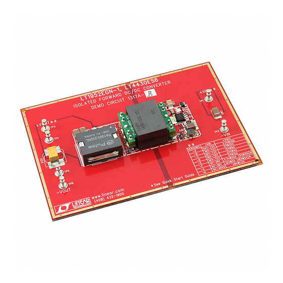
The DC1317A-G (Figure 7) converts isolated 9V to
36V input to 12V output and provides over 8A of out-
put current depending on cooling. When determining
the cooling requirements the actual input voltage
range and continuous maximum output current must
be taken into account. The converter operates at
200kHz with the peak efficiency greater than 94%.
The DC1317 can be easily modified to generate out-
put voltages in the range from 0.6V to 48V. The out-
put currents are limited by total output power of up to
150W.
The available versions of DC1317A are:
DC1317A-A, 34-75Vin to 3.3V, 35A
DC1317A-B, 18-72Vin to 5V, 25A
DC1317A-C, 18-72Vin to 12V, 8A-12A
DC1317A-D, 18-72Vin to 24V, 5A
DC1317A-E, 36-72Vin to 5V, 12A
Table 1. Performance Summary
PARAMETER
Minimum Input Voltage
Maximum Input Voltage
V OUT
Typical Output Ripple V OUT
Nominal Switching Frequency
Arrow.com.
Downloaded from
DC1317A-F, 9-36Vin to 3.3V, 22A
* DC1317A-F5, 9-36Vin to 5V, 20A
DC1317A-G, 9-36Vin to 12V, 8A
* DC1317A-G18, 9-36Vin to 18V, 5A
DC1317A-H, 9-36Vin to 48V, 1.5A
* The DC1317A-G18 is a slightly modified design fea-
turing 18V @6A output. Please contact the LTC fac-
tory for details.
The DC1317 circuit features soft-start which prevents
output voltage overshoot on startup or when recover-
ing from overload condition.
The DC1317 has precise over-current protection cir-
cuit that allows for continuous operation under short
circuit conditions. The low power dissipation under
short circuit conditions insures high reliability even
during short circuits.
The LT1952 can be synchronized to an external clock
of up to 400kHz. Please refer to LT1952 data sheet for
design details and applications information.
Design files for this circuit board are available. Call
the LTC factory.
LT is a trademark of Linear Technology Corporation
CONDITION
I OUT = 0A to 8A
I OUT = 0A to 8A
V IN = 9V to 36V, I OUT = 0A to 8A (27Amax) 12V ±3%
V IN = 9V to 36V, I OUT = 0A to 8A
LT1952-1
VALUE
9V
36V
50mV P–P
200kHz
1
Advertisement
Table of Contents

Related Manuals for Linear Technology DC1317A


Summary of Contents for Linear Technology DC1317A
- Page 1 The DC1317A-G (Figure 7) converts isolated 9V to * The DC1317A-G18 is a slightly modified design fea- 36V input to 12V output and provides over 8A of out- turing 18V @6A output. Please contact the LTC fac- put current depending on cooling.
-
Page 2: Quick Start Procedure
QUICK START GUIDE FOR DEMONSTRATION CIRCUIT 1317A-G ACTIVE RESET ISOLATED 9-36V INPUT TO 12V @8A DC/DC POWER CONVERTER QUICK START PROCEDURE Turn on the power at the input. Demonstration circuit 1317 is easy to set up to evalu- NOTE: Make sure that the input voltage does not ate the performance of LT1952-1 circuit. -
Page 3: Output Circuit
Figure 3), wide input range, high power density and small size. To achieve such high efficiency all of The efficiency of 18V Output version of DC1317A-G is the power components were carefully selected. shown in the Figure 4. The efficiency is slightly lower... -
Page 4: Soft Start Function
Figure 6. The rise time of output voltage is controlled by capacitor C19 that The load step response of DC1317A-G is very fast is connected to OC (Overshoot Control) pin of even though relatively small amount of output ca- LT4430. -
Page 5: Pcb Layout
The PCB layout for DC1317A nents by placing the components tight together. can be used as a guide. Since demo board DC1317A Please contact LT factory for additional assistance. has 8 versions the PCB layout has optional compo- nents that can be removed. - Page 6 Arrow.com. Arrow.com. Arrow.com. Arrow.com. Arrow.com. Arrow.com. Downloaded from Downloaded from Downloaded from Downloaded from Downloaded from Downloaded from...
- Page 7 Arrow.com. Arrow.com. Arrow.com. Arrow.com. Arrow.com. Arrow.com. Arrow.com. Downloaded from Downloaded from Downloaded from Downloaded from Downloaded from Downloaded from Downloaded from...
- Page 8 Arrow.com. Arrow.com. Arrow.com. Arrow.com. Arrow.com. Arrow.com. Arrow.com. Arrow.com. Downloaded from Downloaded from Downloaded from Downloaded from Downloaded from Downloaded from Downloaded from Downloaded from...
- Page 9 Arrow.com. Arrow.com. Arrow.com. Arrow.com. Arrow.com. Arrow.com. Arrow.com. Arrow.com. Arrow.com. Downloaded from Downloaded from Downloaded from Downloaded from Downloaded from Downloaded from Downloaded from Downloaded from Downloaded from...
Need help?
Do you have a question about the DC1317A and is the answer not in the manual?
Questions and answers