Advertisement
DESCRIPTION
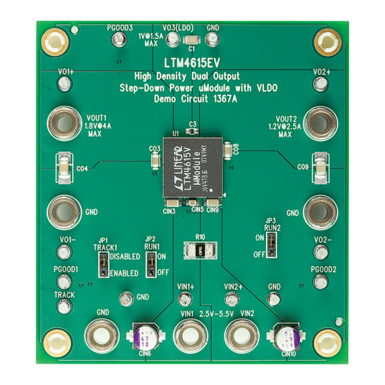
Demonstration circuit 1367A features the LTM
triple output μModule
®
regulator consisting of two switch
mode outputs and one LDO output. Each LTM4615 DC/DC
converter has a separate input and enable pin. The LTM4615
maximum load current is 4A for each switch mode channel
and 1.5A for the VLDO™ channel. However the DC1367A
is configured with the LDO input supply connected to
the VOUT2 whose maximum output current decreases
accordingly. Derating is necessary for certain V
PERFORMANCE SUMMARY
PARAMETER
Input Voltage Range
Output Voltage V
OUT1
Output Voltage V
OUT2
Output Voltage V
O3(LDO)
Maximum Continuous Output Current
Default Operating Frequency
Efficiency of Channel 1
Efficiency of Channel 2
BOARD PHOTO
DEMO MANUAL DC1367A
µModule Regulator with LDO
and thermal conditions. The LTM4615 data sheet must be
4615EV, a
®
read in conjunction with this manual prior to working on
or modifying DC1367A.
Design files for this circuit board are available at
http://www.linear.com/demo
L, LT, LTC, LTM, μModule, Linear Technology and the Linear logo are registered trademarks
and VLDO is a trademark of Linear Technology Corporation. All other trademarks are the
, V
property of their respective owners.
IN
OUT
(T
= 25°C)
A
CONDITION
Both Switch Mode Outputs (V
IN1
DC Voltage, V
= 3.3V, I
= 4A
IN1
OUT1
DC Voltage, V
= 3.3V, I
= 2.5A
IN2
OUT2
DC Voltage, V
= 3.3V, I
= 1.5A
IN2
OUT3
Note: I
= 4.0A – I
OUT2
03
For 2 Switching Mode Channels
V
= 5.5V, V
= 1.8V, I
= 4A
IN1
OUT1
OUT1
V
= 5.5V, V
= 1.2V, I
= 2.5A
IN2
OUT2
OUT2
Dual DC/DC Step-Down
VALUE
and V
)
2.5V to 5.5V
IN2
1.8V ±2%
1.2V ±2%
1.0V ±2%
4A DC at V
OUT1
1.25MHz
82.8%, See Figure 3
81.7%, See Figure 3
LTM4615EV:
, 4A DC at V
, 1.5A DC at V
OUT2
O3
dc1367af
1
Advertisement
Table of Contents

Related Manuals for Linear Technology DC1367A


Summary of Contents for Linear Technology DC1367A
- Page 1 1.5A for the VLDO™ channel. However the DC1367A is configured with the LDO input supply connected to L, LT, LTC, LTM, μModule, Linear Technology and the Linear logo are registered trademarks the VOUT2 whose maximum output current decreases and VLDO is a trademark of Linear Technology Corporation. All other trademarks are the accordingly.
- Page 2 To disable tracking on VOUT2, please remove R6 and R7 and connect TRACK2 to VIN2. – 8. VIN1 and VIN2 are shorted on DC1367A through a 1mΩ resistor, R10. If desired, remove R10 to allow separate LOAD...
- Page 3 DEMO MANUAL DC1367A QUICK START PROCEDURE = 5.5V, V = 1.8V OUT 1 CHANNEL 2 AND 3 OFF = 5.5V, V = 1.2V OUT 2 CHANNEL 1 AND 3 OFF = 1.2V, V = 1.0V OUT 3 CHANNEL 1 AND 2 OFF...
- Page 4 DEMO MANUAL DC1367A PARTS LIST ITEM REFERENCE PART DESCRIPTION MANUFACTURER/PART NUMBER Required Circuit Components CIN6, CIN10 CAP ., OS-CON, 47μF , 10V, C6 SIZE SANYO, 10SVP47M CO4, CO9 CAP ., X5R, 100μF , 6.3V, 10%,1210-7343 AVX, 12106D107KAT2A CO3, CO8 CAP ., X5R, 22μF , 6.3V, 20%, 1206-0805...
- Page 5 DEMO MANUAL DC1367A SCHEMATIC DIAGRAM dc1367af...
- Page 6 Linear Technology Corporation (LTC) provides the enclosed product(s) under the following AS IS conditions: This demonstration board (DEMO BOARD) kit being sold or provided by Linear Technology is intended for use for ENGINEERING DEVELOPMENT OR EVALUATION PURPOSES ONLY and is not provided by LTC for commercial use. As such, the DEMO BOARD herein may not be complete in terms of required design-, marketing-, and/or manufacturing-related protective considerations, including but not limited to product safety measures typically found in finished commercial goods.
- Page 7 Mouser Electronics Authorized Distributor Click to View Pricing, Inventory, Delivery & Lifecycle Information: Analog Devices Inc. DC1367A...
Need help?
Do you have a question about the DC1367A and is the answer not in the manual?
Questions and answers