Planet GS-4210 Series Quick Installation Manual
802.3bt poe++ l2/l4 managed gigabit ethernet switch
Hide thumbs
Also See for GS-4210 Series:
- Installation manual ,
- User manual (353 pages) ,
- Quick installation manual (20 pages)

Related Manuals for Planet GS-4210 Series


Summary of Contents for Planet GS-4210 Series
- Page 1 L2/L4 Managed Gigabit Ethernet Switch GS-4210 802.3bt PoE++ Series Quick Installation Guide...
-
Page 2: Table Of Contents
Table of Contents 1. Package Contents ..................3 2. Requirements ..................... 4 3. Terminal Setup ................... 5 3.1 Logging on to the Console..............6 3.2 Configuring IP Address via the Console ..........7 3.3 Storing Current Switch Configuration ............. 9 4. Starting Web Management .................10 4.1 Logging in to the Managed Switch ............10 4.2 Saving Configuration via the Web ............13 5. Recovering Back to Default Configuration .............14 6. -
Page 3: Package Contents
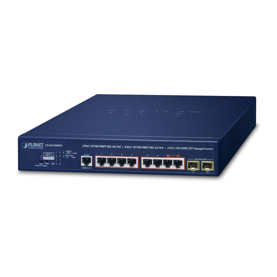
1. Package Contents Thank you for purchasing PLANET L2/L4 Managed Gigabit Ethernet Switch. The descriptions of this series are shown below: 4-port 10/100/1000T 802.3bt PoE + 4-port 10/100/1000T GS-4210-8HP2T2S 802.3at PoE + 2-port 10/100/1000T + 2-port 100/1000X SFP Managed Switch 2-port 10/100/1000T 802.3bt PoE + 6-port 10/100/1000T GS-4210-8HP2S 802.3at PoE + 2-port 100/1000X SFP Managed Switch 16-port 10/100/1000T 802.3bt PoE + 4-port Gigabit TP/SFP GS-4210-16UP4C Combo Managed Switch 24-port 10/100/1000T 802.3bt PoE + 4-port Gigabit TP/SFP GS-4210-24UP4C Combo Managed Switch 4-port 10/100/1000T 802.3bt PoE + 20-port 10/100/1000T GS-4210-24HP2C 802.3at PoE + 2-port Gigabit TP/SFP Combo Managed Switch “Managed Switch” mentioned in this Quick Installation Guide refers to the above models. -
Page 4: Requirements
2. Requirements z Workstations running Windows XP/2003/2008/Vista/7/8/10, MAC OS X or later, Linux, UNIX, or other platforms are compatible with TCP/IP protocols. z Workstations are installed with Ethernet NIC (Network Interface Card) z Serial Port Connection (Terminal) The above Workstations come with COM Port (DB9) or USB-to-RS-232 converter. The above Workstations have been installed with terminal emulator, such as Hyper Terminal included in Windows XP/2003, putty or tera term. Serial cable -- One end is attached to the RS-232 serial port, while the other ends to the RJ45 type console port of the Managed Switch. z Ethernet Port Connection Network cables -- Use standard network (UTP) cables with RJ45 connectors. The above PC is installed with Web browser. It is recommended to use Internet Explorer 8.0 or above to access the Managed Switch. -
Page 5: Terminal Setup
3. Terminal Setup The Managed Switch is equipped with a console interface for local switch setup and maintenance. To configure the system, connect a serial cable to a COM port on a PC or notebook computer and to the RJ45 type of the console port of the Managed Switch. PC / Workstation with Terminal Emulation Software Managed Switch RS232 to RJ45 Cable RJ45 Serial Port Console Port Figure 3-1: Managed Switch Console Connectivity A terminal program is required to make the software connection to the Managed Switch. -
Page 6: Logging On To The Console
3.1 Logging on to the Console Once the terminal is connected to the device, power on the Managed Switch and the terminal will display “running testing procedures”. Then, the following message asks to log in user name and password. The factory default user name and password are shown as follows, and the login screen in Figure 3-2 appears. -
Page 7: Configuring Ip Address Via The Console
3.2 Configuring IP Address via the Console The Managed Switch is shipped with default IP address as follows: IP Address: 192.168.0.100 Subnet Mask: 255.255.255.0 To check the current IP address or modify a new IP address for the Switch, please use the procedures as follows: Showing the current IP address 1. At the “GS-4210 Series#” prompt, enter “show ip”. 2. The screen displays the current IP Address, Subnet Mask and Gateway as shown in Figure 3-3. Figure 3-3: IP Information Screen... - Page 8 Configuring IP address 3. At the“GS-4210 Series#” prompt, enter “configure”. 4. At the “GS-4210 Series(config)#” prompt, enter the following command and press <Enter> as shown in Figure 3-4. GS-4210 Series(config)# ip address 192.168.1.100 mask 255.255.255.0 GS-4210 Series(config)# ip default-gateway 192.168.1.254 The previous command would apply the following settings for the Switch. IP Address: 192.168.1.100 Subnet Mask: 255.255.255.0 Gateway: 192.168.1.254 Figure 3-4: IP Address Screen 5. Repeat Step 1 to check if the IP address has changed...
-
Page 9: Storing Current Switch Configuration
1. At the “GS-4210 Series#” prompt, enter “copy running-config startup- config” as shown in Figure 3-5. Figure 3-5: Storing Current Configuration Command Screen If you are not familiar with console command or the related para- meter, enter “?” anytime in console to get the help description. -
Page 10: Starting Web Management
4. Starting Web Management The following shows how to start up the Web Management of the Managed Switch. Note the Managed Switch is configured through an Ethernet connection. Please make sure the manager PC must be set to the same IP subnet address. For example, the default IP address of the Managed Switch is 192.168.0.100, then the manager PC should be set to 192.168.0.x (where x is a number between 1 and 254, except 100), and the default subnet mask is 255.255.255.0. - Page 11 2. When the following dialog box appears, please enter the default user name and password “admin”. The login screen in Figure 4-2 appears. Default Username: admin Default Password: admin Figure 4-2: Login Screen 3. After entering the password, the main screen appears as Figure 4-3 shows. Figure 4-3: Web Main Screen of Managed Switch...
- Page 12 The Switch Menu on the top of the Web page lets you access all the commands and statistics the Managed Switch provides. The Switch Menu always contains one or more buttons, such as “System”, “Switching”, “QoS”, “Security”, “PoE” and “Maintenance”. Figure 4-4: Switch Menu Now, you can use the Web management interface to continue the Switch management.
-
Page 13: Saving Configuration Via The Web
4.2 Saving Configuration via the Web To save all applied changes and set the current configuration as a startup configuration, the startup-configuration file will be loaded automatically across a system reboot. 1. Click “Save > Save Configurations to FLASH” to log in to the “Configuration Manager” page. -
Page 14: Recovering Back To Default Configuration
5. Recovering Back to Default Configuration IP address has been changed or admin password has been forgotten – To reset the IP address to the default IP address “192.168.0.100” or reset the login password to the default value, press the hardware-based reset button on the front panel for about 10 seconds. After the device is rebooted, you can log in the management Web interface within the same subnet of 192.168.0.xx. 2-Port 10/100/1000T 802.3bt PoE + 6-Port 10/100/1000T 802.3at PoE + 2-Port 100/1000X SFP Managed GS-4210-8HP2S LNK/ACT 1000... - Page 15 802.3bt PoE ++ GS-4210-24UP4C Console Reset 1000 PoE-in-Use 115200, N, 8, 1 10/100 at/af PoE-in-Use Reset Button Figure 5-3: GS-4210-24UP4C Reset Button 4-Port 10/100/1000T 802.3bt PoE + 20-Port 10/100/1000T 802.3at PoE + 2-Port Gigabit TP/SFP Combo Managed Switch LNK/ACT 1000 10/100 Console LNK/ACT...
-
Page 16: Customer Support
PLANET online FAQs: https://www.planet.com.tw/en/support/faq?method=category&c1=1 Support team mail address: support@planet.com.tw GS-4210 802.3bt PoE Series User’s Manual: https://www.planet.com.tw/en/support/download. php?&method=keyword&keyword=GS-4210&view=3#list (Please select your switch model name from Product Model drop-down menu) Copyright © PLANET Technology Corp. 2020. Contents are subject to revision without prior notice. PLANET is a registered trademark of PLANET Technology Corp. All other trademarks belong to their respective owners.
Need help?
Do you have a question about the GS-4210 Series and is the answer not in the manual?
Questions and answers