
Related Manuals for Welbilt Convotherm OES mini easyTouch


Summary of Contents for Welbilt Convotherm OES mini easyTouch
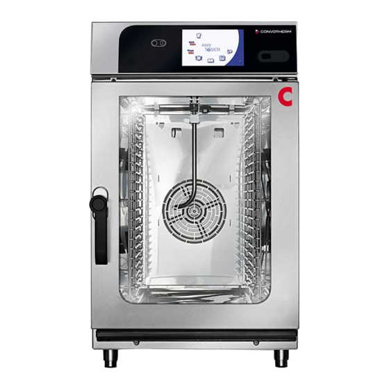
- Page 1 Combi oven Read instructions before use OES mini easyTouch Installation manual - Original, ENG...
-
Page 3: Table Of Contents
Table of Contents Table of Contents General Environmental protection Identifying your combi oven Structure of customer documentation Essential reading relating to safety About this installation manual Design and function Design and function of the combi oven (6.06/6.10/10.10 mini) Layout and function of the combi oven (6.10 mini 2in1) Layout and function of the operating panel For your safety Basic safety code... - Page 4 Table of Contents 6.1.4 Converting the electrical supply to a single-phase supply (6.06 mini) 6.1.5 Converting the electrical supply to a three-phase supply (6.06/6.10 mini) Water connection 6.2.1 Safe working when making the water connection 6.2.2 Water supply 6.2.3 Test the water quality 6.2.4 Water drain Installing the ConvoClean system...
-
Page 5: General
1 General 1 General Purpose of this chapter This chapter shows you how to identify your combi oven and provides guidance on using this manual. 1.1 Environmental protection Statement of principles Our customers' expectations, the legal regulations and standards and our company's own reputation set the quality and service for all our products. -
Page 6: Identifying Your Combi Oven
1 General 1.2 Identifying your combi oven Position of type plate The type plate is located on the left-hand side of the combi oven. Layout and structure of the type plate You can use the type plate to identify your appliance. The type plate has the following layout: Item Name Name of appliance... -
Page 7: Structure Of Customer Documentation
1 General 1.3 Structure of customer documentation Contents of customer documentation The customer documentation for the combi oven includes the following documents: Installation manual (this document) ■ User manual ■ Operating instructions for easyStart mode ■ Help facility included in the software (extracts from the user manual) ■... -
Page 8: Essential Reading Relating To Safety
1 General 1.4 Essential reading relating to safety Safety information in the customer documentation Safety information relating to the combi oven mainly appears in the installation manual and the user manual. The installation manual contains the safety information for the tasks covered by the manual and which are performed when moving, setting up and installing the appliance and when putting the appliance into service and removing the appliance from service. -
Page 9: About This Installation Manual
1 General 1.5 About this installation manual Purpose This installation manual is intended for all people who work with the combi oven, and provides them with the necessary information for proper and safe working when moving, setting up and installing the appliance and when putting the appliance into service. - Page 10 1 General Contents Purpose Dimensional drawings and Contains the dimensional drawings and connection plans. connection diagrams Checklists and completion Contains the checklists for ■ of installation Installation ■ Safety devices and warnings ■ Customer guidance and instruction ■ Contains information on the warranty and explains the completion ■...
-
Page 11: Design And Function
2 Design and function 2 Design and function Purpose of this chapter This chapter describes the design and construction of the combi oven and explains its functions. 2.1 Design and function of the combi oven (6.06/6.10/10.10 mini) Layout of the combi oven The following figure shows the 6.06 mini combi oven (representative of all appliance sizes): Components of the combi ovens and their function The components of the combi oven have the following function:... -
Page 12: Layout And Function Of The Combi Oven (6.10 Mini 2In1)
2 Design and function Name Function Cooking chamber Contains the food during cooking operation Appliance feet Used for setting up and adjusting level of appliance ■ Height adjustable on 10.10 mini ■ Type plate Used for identifying the combi oven Material The interior and exterior structure of the combi oven is made of stainless steel. - Page 13 2 Design and function Name Function Door handle Opens and closes the appliance door Ventilation slots Used for ventilation Rear wall Covers the wiring compartment of the combi oven Top box Covers the controller electronics of the combi oven Outer casing Used for covering the appliance interior Connecting bracket Used for covering the connection area...
-
Page 14: Layout And Function Of The Operating Panel
2 Design and function 2.3 Layout and function of the operating panel Layout of the operating panel The following illustration shows the operating panel: Layout of the operating panel (6.10 mini 2in1) The following illustration shows the operating panel: Elements of the operating panel The elements of the operating panel have the following function: Name Function... -
Page 15: For Your Safety
3 For your safety 3 For your safety Purpose of this chapter This chapter provides you with all the information you need in order to use the combi oven safely with‐ out putting yourself or others at risk. This is a particularly important chapter that you should read through carefully. 3.1 ... - Page 16 3 For your safety More on this ... Related topics Intended use of your combi oven Warning signs on the combi oven (6.06/6.10/10.10 mini) Warning signs on the combi oven (6.10 mini 2in1) Hazards and safety precautions when moving the appliance Hazards and safety precautions when setting up the appliance Hazards and safety precautions during installation Hazards and safety precautions when putting the appliance into service...
-
Page 17: Intended Use Of Your Combi Oven
3 For your safety 3.2 Intended use of your combi oven Intended use The combi oven is designed and built solely for cooking different foodstuffs in standard-sized food ■ containers (e.g. Gastronorm containers, standard baking trays). Steam, convection and combi- steam (non-pressurized superheated steam) are used for this purpose. -
Page 18: Warning Signs On The Combi Oven (6.06/6.10/10.10 Mini)
3 For your safety 3.3 Warning signs on the combi oven (6.06/6.10/10.10 mini) Where are the warning signs fitted? The following figure shows the 6.06 mini combi oven (representative of all appliance sizes). The warning signs are located in the following positions: Warnings on the appliance door The following warning signs (2) are fitted on the appliance door above the door handle: Warning sign... - Page 19 3 For your safety Warning signs on the combi oven case The following warning signs (1) are fitted on the case of the combi oven: Warning sign Description High voltage / electric shock hazard warning There is a risk of electric shock from live parts if the safety cover is opened. Installation manual...
-
Page 20: Warning Signs On The Combi Oven (6.10 Mini 2In1)
3 For your safety 3.4 Warning signs on the combi oven (6.10 mini 2in1) Where are the warning signs fitted? The warning signs are located in the following positions on the combi oven: Warnings on the appliance door The following warning signs (2) are fitted on the appliance doors above the door handles: Warning sign Description Warning of hot food, hot food containers and hot liquids... - Page 21 3 For your safety Warning signs on the case of the cleaning agent drawers The following warning sign (3) is mounted on the case of the cleaning agent drawers: Warning sign Description High voltage / electric shock hazard warning There is a risk of electric shock from live parts if the safety cover is opened. Installation manual...
-
Page 22: Hazards And Safety Precautions When Moving The Appliance
3 For your safety 3.5 Hazards and safety precautions when moving the appliance Safety hazard: moving heavy weights When moving the appliance, be aware of the following hazards and take the specified preventive ac‐ tions: Danger Where or in what situations Preventive action Safety device does the hazard arise? -
Page 23: Hazards And Safety Precautions When Setting Up The Appliance
3 For your safety 3.6 Hazards and safety precautions when setting up the appliance Safety hazard: moving heavy weights When setting up the appliance, be aware of the following hazards and take the specified preventive actions: Danger Where or in what situations Preventive action Safety device does the hazard arise? - Page 24 3 For your safety Safety hazard: mechanical parts of the appliance When setting up the appliance, be aware of the following hazards and take the specified preventive actions: Danger Where or in what situations Preventive action Safety device does the hazard arise? Risk of body parts be‐...
-
Page 25: Hazards And Safety Precautions During Installation
3 For your safety 3.7 Hazards and safety precautions during installation Safety hazard: electrical power When installing the appliance, be aware of the following hazards and take the specified preventive ac‐ tions: Danger Where or in what situations Preventive action Safety device does the hazard arise? Risk of electric shock... - Page 26 3 For your safety Safety hazard: mechanical parts of the appliance When installing the appliance, be aware of the following hazards and take the specified preventive ac‐ tions: Danger Where or in what situations Preventive action Safety device does the hazard arise? Risk of cuts from sharp When handling sheet-metal Exercise caution when...
-
Page 27: Hazards And Safety Precautions When Putting The Appliance Into Service
3 For your safety 3.8 Hazards and safety precautions when putting the appliance into service Safety hazard: electrical power When preparing the appliance for first-time use, be aware of the following hazards and take the speci‐ fied preventive actions: Danger Where or in what situations Preventive action Safety device... - Page 28 3 For your safety Safety hazard: moving appliances supported on a wheeled platform Danger Where or in what situations Preventive action Safety device does the hazard arise? All specified hazards While appliances are being Before moving applian‐ Retaining de‐ ■ moved on a wheeled platform ces with a fixed wastewa‐...
- Page 29 3 For your safety Additional safety hazards when putting the appliance into service When preparing the appliance for first-time use, read and follow the safety information given in this chapter and also the following topics in the chapter 'For your safety' in the user manual: Hazards and safety precautions during operation ■...
-
Page 30: Hazards And Safety Precautions When Removing The Appliance From Service
3 For your safety 3.9 Hazards and safety precautions when removing the appliance from service Safety hazard: electrical power When taking the appliance out of service, be aware of the following hazards and take the specified preventive actions: Danger Where or in what situations Preventive action Safety device does the hazard arise? - Page 31 3 For your safety Safety hazard: moving appliances supported on a wheeled platform Danger Where or in what situations Preventive action Safety device does the hazard arise? All specified hazards While appliances are being Disconnect the appliance Retaining de‐ ■ moved on a wheeled platform from the electrical supply vice...
- Page 32 3 For your safety Safety hazard: mechanical parts of the appliance When taking the appliance out of service, be aware of the following hazards and take the specified preventive actions: Danger Where or in what situations Preventive action Safety device does the hazard arise? For 6.10 mini 2in1: When lifting the appliance...
-
Page 33: Safety Devices (6.06/6.10/10.10 Mini)
3 For your safety 3.10 Safety devices (6.06/6.10/10.10 mini) Meaning The combi oven has a number of safety devices to protect the user from hazards. It is absolutely es‐ sential that all safety devices are fitted, secured correctly and in working order when operating the combi oven. - Page 34 3 For your safety Safety device Function Check For the safety catch op‐ Prevents scalding of user's When appliance is at low tem‐ tion: face and hands from escaping perature, check door positions steam as described in 'Opening and On-latch position of ap‐ closing the appliance door pliance door safely' in the user manual...
-
Page 35: Safety Devices (6.10 Mini 2In1)
3 For your safety 3.11 Safety devices (6.10 mini 2in1) Meaning The combi oven has a number of safety devices to protect the user from hazards. It is absolutely es‐ sential that all safety devices are fitted, secured correctly and in working order when operating the combi oven. - Page 36 3 For your safety Safety device Function Check Spray-guard Stops the cleaning agent being Test is a software function injected during fully automatic cleaning (ConvoClean system) picture) when the appliance door is opened Prompt to close the appliance door Block on simultaneous Prevents cooking being per‐...
-
Page 37: Requirements To Be Met By Personnel, Working Positions
3 For your safety 3.12 Requirements to be met by personnel, working positions Requirements to be met by personnel The table shows the skills required to perform the specified roles. One person may perform more than one role depending on need and organization of work, provided this person has the skills required for the role concerned. - Page 38 3 For your safety Working positions when installing the appliance and putting the appliance into service The working position for personnel installing the appliance and putting the appliance into service is the entire appliance area. Installation manual...
-
Page 39: Personal Protective Equipment
3 For your safety 3.13 Personal protective equipment Moving and setting up the appliance When moving and setting up the combi oven, wear the following personal protective equipment: Activity Materials used Personal protective equipment Conveying within the establish‐ Lifting straps Protective gloves ■... -
Page 40: Transportation
4 Transportation 4 Transportation Purpose of this chapter This chapter provides information on how to move your appliance. This chapter is intended for the user, as well as for installation technicians and authorized customer service staff. 4.1 Safe working when moving the appliance For your safety Before starting work, familiarize yourself with the hazards described in Hazards and safety precautions when moving the appliance on page 22. -
Page 41: Conveying The Appliance To The Installation Location
4 Transportation 4.2 Conveying the appliance to the installation location Space required for conveying the appliance Make sure that there is enough width and height along the entire route used for conveying the appli‐ ance to ensure it can get through to its installation location. The table below shows the required minimum door size to allow the combi oven to be brought to its intended location: Minimum door opening... -
Page 42: Setting Up The Appliance
5 Setting up the appliance 5 Setting up the appliance Purpose of this chapter This chapter provides information on how to set up your appliance. This chapter is intended for the user, as well as for installation technicians and authorized customer service staff. -
Page 43: Adjacent Systems
5 Setting up the appliance 5.2 Adjacent systems Dealing with the discharged air During operation, the combi oven generates heat and moisture, which mainly escape upwards into the surrounding air as hot vapour from the air vent. It is not permitted to connect air ventilation pipes di‐ rectly to the air vent of the combi oven. -
Page 44: Requirements For The Installation Location
5 Setting up the appliance 5.3 Requirements for the installation location Meaning This section contains information to help you choose a suitable installation location for the appliance. Inspect the intended installation location carefully to ensure it is suitable before bringing the appliance there and starting the installation. - Page 45 5 Setting up the appliance Rules for setting up the appliance safely (6.10 mini 2in1) To prevent hazards that arise from the installation site and environment of the appliances, the follow‐ ing rules must be observed: It must be possible to comply with the operating conditions. For operating conditions, see Require‐ ■...
- Page 46 5 Setting up the appliance Actual space requirements Far more room than the specified minimum space requirement is needed in front of the appliances to operate the combi ovens safely, in particular to handle hot food safely. Larger wall gaps are generally recommended to provide access for servicing. In the installation location, the following parts must not be covered, obstructed or blocked (see also 'Design and function of the combi oven'): Air vent on the top of the appliance...
- Page 47 5 Setting up the appliance Minimum space required - height The following diagram and table show the vertical space needed by the appliance: The service engineer who is responsible for setting up the appliance must take into account the nature of the ceiling and any adjacent systems that may be used (air ventilation system, vapour extractor hood etc.) when designing the particular clearance needed between the top of the appliance and the ceiling.
-
Page 48: Unpacking
5 Setting up the appliance 5.4 Unpacking Checking the tip indicator Before unpacking the appliance, check the tip indicator on the packaging. The following table shows the possible tip'n'tell indications: Indicator Meaning Action Silver dot: Unpack the appliance. ■ Appliance has been transported cor‐ Compare the number on the tip in‐... - Page 49 5 Setting up the appliance Scope of delivery (6.06/6.10/10.10 mini) The following parts are supplied with the appliance: 1x combi oven ■ 1x left-hand rack ■ 1x right-hand rack ■ 1x installation manual ■ 1x user manual ■ 1x easyStart operating instructions ■...
-
Page 50: Taking The Appliance Off The Pallet
5 Setting up the appliance 5.5 Taking the appliance off the pallet Using lifting straps to take the appliance off the pallet (10.10 mini) The weight of your appliance is given in the Technical Data on page 92. When lifting the appliance off the pallet, follow the steps below: Step Action Illustration... -
Page 51: Setting Up The Appliance On A Worktable
5 Setting up the appliance 5.6 Setting up the appliance on a worktable Rules for setting up the appliance safely Observe the following rules to ensure that the appliance is installed in a stable situation: It must be possible to set up the worktable in the installation position so that it cannot tip over or ■... -
Page 52: Setting Up The Appliance On A Stand
5 Setting up the appliance 5.7 Setting up the appliance on a stand Rules for setting up the appliance safely Observe the following rules to ensure that the appliance is installed in a stable situation: The stand for the appliance must be fixed so that it cannot tip over when subject to a one-sided ■... -
Page 53: Setting Up The Appliance On A Wheeled Stand
5 Setting up the appliance 5.8 Setting up the appliance on a wheeled stand Rules for setting up the appliance safely Observe the following rules to ensure that the appliance is installed in a stable situation: The stand for the appliance must be fixed so that it cannot tip over when subject to a one-sided ■... - Page 54 5 Setting up the appliance Setting up the appliance on a wheeled stand When setting up the appliance on a wheeled oven stand, follow the steps below: Step Action Illustration Position the wheeled oven stand in the installation loca‐ tion and level it so that the absolute tilt of the appliance in operation does not exceed 2°...
-
Page 55: Setting Up The Appliance On The Floor (6.10 Mini 2In1)
5 Setting up the appliance 5.9 Setting up the appliance on the floor (6.10 mini 2in1) Rules for setting up the appliance safely Observe the following rules to ensure that the appliance is installed in a stable situation: The stand for the appliance must be fixed so that it cannot tip over when subject to a one-sided ■... -
Page 56: Fitting Appliance To The Wall
5 Setting up the appliance 5.10 Fitting appliance to the wall Rules for setting up the appliance safely Observe the following rule to ensure that the appliance is stable when fitted to the wall: When a wall bracket is used to fix the appliance, it must only be fitted to a load-bearing wall with a ■... - Page 57 5 Setting up the appliance Fitting appliance to wall with wall bracket (6.10 mini) When fixing the appliance using the wall bracket, follow the steps below: Step Action Illustration Fix the wall bracket (1) to the wall using the enclosed screws.
-
Page 58: Installing The Appliances In A Stacking Kit
5 Setting up the appliance 5.11 Installing the appliances in a stacking kit Rules for installing the appliances safely in the stacking kit Observe the following rules to ensure that the stacking kit fitted with appliances is stable: It is only permitted to fit appliances of similar weight in the top and bottom of the stacking kit. ■... -
Page 59: Installing Appliances In A Wheeled Stacking Kit
5 Setting up the appliance 5.12 Installing appliances in a wheeled stacking kit Rules for installing the appliances safely in the wheeled stacking kit Observe the following rules to ensure that the stacking kit fitted with appliances is stable: It is only permitted to fit appliances of similar weight in the top and bottom of the stacking kit. ■... -
Page 60: Installation
6 Installation 6 Installation Purpose of this chapter This chapter explains how to connect your combi oven. 6.1 Electrical installation Purpose of this section This section shows you how to perform the electrical installation. 6.1.1 Safe working during electrical installation For your safety Before starting work, familiarize yourself with the hazards described in Hazards and safety precautions during installation on page 25. - Page 61 6 Installation Personal protective equipment Wear the personal protective equipment specified in the section 'Personal protective equipment' on page 39 of the 'For your safety' chapter for the relevant tasks. Live parts Risk of electric shock from live parts When the cover is open, there is a risk of electric shock from touching live parts. Make sure that any work on the electrical system is performed solely by a qualified electrician from an authorized customer service office.
-
Page 62: Planning The Electrical Installation
6 Installation 6.1.2 Planning the electrical installation Meaning It is crucial to safe and reliable operation of the appliance that the electrical installation is implemented correctly and professionally. All the rules and regulations listed here, and the described procedure, must be strictly followed. Rules for safe electrical installation of the appliances Observe the following rules to prevent hazards caused by faulty electrical connections: The case of the appliance must be grounded and connected to the equipotential bonding system in... - Page 63 6 Installation Regular tests and operational leakage current values It is compulsory to test the appliance regularly in accordance with the recognized codes of practice Calibrated meters must be used for the electrical testing in order to perform the stipulated measure‐ ments of protective conductor resistance, insulation resistance, protective conductor current / leakage current (see also Individual electrical test on page 86 in the chapter 'Putting into service').
-
Page 64: Carrying Out The Electrical Installation
6 Installation 6.1.3 Carrying out the electrical installation Requirements Check that the following requirement has been met: The connection point of the appliance is disconnected from the customer power supply and protec‐ ■ tive measures taken to ensure the power cannot be switched on again. Checking the supply ratings and electrical connections Follow the steps below to check the connection to the installation system and the electrical connec‐... -
Page 65: Converting The Electrical Supply To A Single-Phase Supply (6.06 Mini)
6 Installation 6.1.4 Converting the electrical supply to a single-phase supply (6.06 mini) Objective To convert the electrical supply from 3N~ 400V 50/60Hz (3/N/PE) to 1N~ 230V 50/60 Hz (1/N/PE). Requirements Check that the following requirement has been met: The connection point of the appliance is disconnected from the customer power supply and protec‐ ■... -
Page 66: Converting The Electrical Supply To A Three-Phase Supply (6.06/6.10 Mini)
6 Installation 6.1.5 Converting the electrical supply to a three-phase supply (6.06/6.10 mini) Objective To convert the electrical supply from 3N~ 400V 50/60Hz (3/N/PE) to 3~ 230V 50/60Hz (3/PE). Requirements Check that the following requirement has been met: The connection point of the appliance is disconnected from the customer power supply and protec‐ ■... -
Page 67: Water Connection
6 Installation 6.2 Water connection Purpose of this section This section shows you how to install the water connection. 6.2.1 Safe working when making the water connection For your safety Before starting work, familiarize yourself with the hazards described in Hazards and safety precautions during installation on page 25. - Page 68 6 Installation Regulations for the drain connection You must comply with local and national regulations on the design of the drain connection and on the composition of the wastewater. These include: DIN 1988 part 2 and part 4 ■ DIN EN 1717 ■...
-
Page 69: Water Supply
6 Installation 6.2.2 Water supply Rules for safe installation of the water supply Observe the following rules to prevent hazards caused by a faulty water connection: For appliances with a wheeled platform, the water supply must be provided via a flexible water sup‐ ■... - Page 70 6 Installation Installation diagram without water treatment (6.06/6.10/10.10 mini for Australia / New Zealand) The following diagram shows the connection diagram for water installations without water treatment: 4 - 7 ° dH 4 - 20 °d H 7 - 13 °T H 7 - 27 °T H 5 - 19 °e 5 - 9 °...
- Page 71 6 Installation Shut-off device with dirt filter Verifiable check valve Type EA Installation diagram without water treatment (6.10 mini 2in1 for Australia / New Zealand) The following diagram shows the connection diagram for water installations without water treatment: 4 - 7 ° dH 4 - 20 °d H 4 - 20 °d H 7 - 13 °T H...
- Page 72 6 Installation Water supply line 0.08 mm sediment filter A 0.08 mm sediment filter must be installed if the water has a high level of impurity. Water treatment If the water quality does not meet required values, a water treatment system must be installed. Shut-off device with dirt filter Verifiable check valve Type EA...
- Page 73 6 Installation Installation diagram with water treatment (6.10 mini 2in1) The following diagram shows the connection diagram for water installations with water treatment: 4 - 7 ° dH 4 - 20 °d H 4 - 20 °d H 7 - 13 °T H 7 - 27 °T H 7 - 27 °T H 5 - 19 °e...
- Page 74 6 Installation Cold water connection Water supply line 0.08 mm sediment filter A 0.08 mm sediment filter must be installed if the water has a high level of impurity. Water treatment If the water quality does not meet required values, a water treatment system must be installed.
-
Page 75: Test The Water Quality
6 Installation 6.2.3 Test the water quality Materials required You will need the following materials: 1 sample container for taking samples ■ 1 conductivity meter (part no. 3019007) ■ Analysis kit for measuring general hardness and carbonate hardness, including two analysis con‐ ■... -
Page 76: Water Drain
6 Installation 6.2.4 Water drain Rules for safe installation of the drain connection Observe the following rules to prevent hazards caused by a faulty drain connection: There must be no restriction or reduction in the cross-section of the drain pipe. ■ The drain pipe must have a minimum slope of 5% (3°). - Page 77 6 Installation Connection diagram (6.10 mini 2in1) The following diagram shows the drain installation system: 5% (3°) Item Meaning Explanation Drain connection On the rear of the combi oven, connection drawing: point C ■ Safety overflow Underneath the combi oven, connection drawing: point M ■...
-
Page 78: Installing The Convoclean System
6 Installation 6.3 Installing the ConvoClean system Purpose of this section This section shows you how to install the ConvoClean fully automatic oven cleaning system. 6.3.1 Safe working when installing the ConvoClean system For your safety Before starting work, familiarize yourself with the hazards described in Hazards and safety precautions during installation on page 25. -
Page 79: Layout Of The Fully Automatic Oven Cleaning System
6 Installation 6.3.2 Layout of the fully automatic oven cleaning system Cleaning agent and rinse aid Use only the cleaning fluids specified here to clean the combi oven. NOTICE Damage caused as a result of improper use of cleaning agents will invalidate any warranty claims. - Page 80 6 Installation Layout of the fully automatic oven cleaning system (6.10 mini 2in1) The following diagram shows the layout of the fully automatic oven cleaning system: Name Drawer for ConvoCare rinse aid Drawer for ConvoClean forte cleaning agent Installation manual...
-
Page 81: Connecting The Fully Automatic Oven Cleaning System (6.06/6.10/10.10 Mini)
6 Installation 6.3.3 Connecting the fully automatic oven cleaning system (6.06/6.10/10.10 mini) Rules for safe connection of the fully automatic oven cleaning system If the ConvoClean and ConvoCare connections are swapped over, there is a health risk from eating the cooked dishes. Observe the following rules to prevent these hazards: When connecting the ConvoClean forte and ConvoCare, extreme care must be taken to ensure ■... -
Page 82: Preparing The Fully Automatic Oven Cleaning System (6.10 Mini 2In1)
6 Installation 6.3.4 Preparing the fully automatic oven cleaning system (6.10 mini 2in1) Rules for safe connection of the fully automatic oven cleaning system If ConvoClean and ConvoCare are swapped over, there is a health risk from eating the cooked dishes. Observe the following rules to prevent these hazards: When filling the cleaning agent drawers with ConvoClean forte and ConvoCare, take great care to ■... -
Page 83: Putting Into Service
7 Putting into service 7 Putting into service Purpose of this chapter This chapter explains how to prepare your combi oven for first-time use, how to take it out of service and how to dispose of it properly. 7.1 Safe working when putting the appliance into service For your safety when putting the appliance into service Before starting work, make sure that you are familiar with the hazards described under 'Hazards and safety precautions when putting the appliance into service' on page 27 and in the chapter 'For your... - Page 84 7 Putting into service To ensure operational and functional safety, all electrical connections must be checked and all manda‐ tory electrical tests required for putting the appliance into service and operating the appliance must be carried out. Basic rules for safe operation If it is known or evident that the combi oven has been moved after installation without authorization (whether intentionally or unintentionally), the appliance must not be put back into service until all the following requirements have been met:...
- Page 85 7 Putting into service Hot surfaces Risk of burns from high temperatures inside the cooking chamber and on the inside of the appliance door You may get burnt if you touch any of the interior parts of the cooking chamber, the inside of the appliance door or any parts that were inside the oven during cooking.
-
Page 86: Procedure For Putting The Appliance Into Service
7 Putting into service 7.2 Procedure for putting the appliance into service Meaning This section is intended for personnel who will prepare the appliance for first-time use. It summarizes what requirements must be met prior to putting the combi oven into use, and describes the procedure for preparing the appliance. - Page 87 7 Putting into service Step Action More on this ... Select the Combi-steam cooking program: See user manual Set 150 °C and 10 minutes. ■ Check the following points: Is the oven light on? ■ Is the fan running? ■ Are there any leaks in the water supply and wastewa‐...
- Page 88 7 Putting into service Step Action More on this ... Check whether steam is being generated in the cook‐ ■ ing chamber (open door carefully). For each cooking chamber, use the pressure gauge ■ to adjust the water supply for the steam generator so that the pressure gage reads 120 kPa (flow pressure 1.2 bar).
-
Page 89: Removal From Service And Disposal
8 Removal from service and disposal 8 Removal from service and disposal Purpose of this chapter This chapter explains how to take your combi oven out of operation and how to dispose of it properly. 8.1 Safe working when removing the appliance from service For your safety when removing the appliance from service Before starting work, familiarize yourself with the hazards described in Hazards and safety precautions when taking the appliance out of service on page 30. - Page 90 8 Removal from service and disposal Personal protective equipment Wear the personal protective equipment specified in the section 'Personal protective equipment' on page 39 of the 'For your safety' chapter for the relevant tasks. Live parts Risk of electric shock from live parts and loose cables When the cover is open, there is a risk of electric shock from touching live parts.
-
Page 91: Removal From Service And Disposal
8 Removal from service and disposal 8.2 Removal from service and disposal Requirements Before removing the appliance from service, check the following points: The appliance is de-energized. ■ The water supply is shut off. ■ Removal from service To take your combi oven out of service, follow the steps for setting up and installing your appliance in the reverse order (see the chapters Installation on page 60, Moving the appliance on page 40 and Setting up the appliance on page 42). -
Page 92: Technical Data And Connection Drawing
9 Technical data and Connection drawing 9 Technical data and Connection drawing 9.1 Technical data Dimensions and weights The following table shows appliance dimensions and weights: 6.06 mini 6.10 mini 10.10 mini 6.10 mini 2in1 Width Including packaging [mm] Excluding packaging [mm] Depth Including packaging [mm]... - Page 93 9 Technical data and Connection drawing Maximum permissible loading weight The following table shows the maximum permissible loading weight per combi oven. Each shelf may only be loaded with a maximum of 5 kg. Maximum permissible loading 6.06 mini 6.10 mini 10.10 mini 6.10 mini weight...
- Page 94 9 Technical data and Connection drawing Dissipated heat The following table shows the heat output figures: Dissipated heat 6.06 mini 6.10 mini 10.10 mini 6.10 min 2in1 Latent heat [kJ/h] 1000 1330 1850 3700 [kW] 0.28 0.37 0.51 1.03 Sensible heat [kJ/h] 1100 1450...
- Page 95 9 Technical data and Connection drawing Water quality International [ppm] 70 - 360 Chemical [mmol/l] 0.7 - 3.6 Properties Temperature [ °C] max. 40 Electrical conductivity [µS/cm] min. 20 pH value 6.5 - 8.5 [mg/l] max. 60 (chloride) (free chlorine) [mg/l] max.
-
Page 96: Connection Drawing For Oes 6.06 Mini
9 Technical data and Connection drawing 9.2 Connection drawing for OES 6.06 mini Dimensions and connection points The following table shows the appliance dimensions and connection points: View Side view View from above with wall clearances Connections on the underside Meaning of labelled elements Water connection Rinse-aid connection Soft water G3/4"... -
Page 97: Connection Drawing For Oes 6.10 Mini
9 Technical data and Connection drawing 9.3 Connection drawing for OES 6.10 mini Dimensions and connection points The following table shows the appliance dimensions and connection points: View Side view View from above with wall clearances Connections on the underside Meaning of labelled elements Water connection Rinse-aid connection Soft water G3/4"... -
Page 98: Connection Drawing For Oes 10.10 Mini
9 Technical data and Connection drawing 9.4 Connection drawing for OES 10.10 mini Dimensions and connection points The following table shows the appliance dimensions and connection points: View Side view View from above with wall clearances Connections on the underside G M F C B A E D Meaning of labelled elements Water connection Rinse-aid connection... -
Page 99: Connection Drawing For Oes 6.10 Mini 2In1
9 Technical data and Connection drawing 9.5 Connection drawing for OES 6.10 mini 2in1 Dimensions and connection points The following table shows the appliance dimensions and connection points: View Side view View from above with wall clearances Connections on the underside Meaning of labelled elements Water connection Equipotential bonding... -
Page 100: Checklists And Completion Of Installation
10 Checklists and completion of installation 10 Checklists and completion of installation Purpose of this chapter This chapter contains the installation checklists and instructions for the user. The checklists are used to prove that the combi oven has been installed correctly. 10.1 Checklist: moving, setting up and installing the appliance Target reader The following checklists are aimed at that person employed by the authorized customer service office... - Page 101 10 Checklists and completion of installation Installing appliances in a wheeled stacking kit on page 59 Installation Requirements Electrical installation on page 60 Water connection on page 67 Installing the ConvoClean system on page 78 Installation manual...
-
Page 102: Checklist: Safety Devices And Warnings
10 Checklists and completion of installation 10.2 Checklist: Safety devices and warnings Safety devices Inspect the following safety devices. Check the box to confirm that the corresponding safety device is fitted and working properly. Safety device Fitted / Work‐ ing properly Covers are fitted Operating panel is fitted Appliance door has no scratches, cracks or dents... -
Page 103: Checklist: Customer Guidance And Instruction
10 Checklists and completion of installation 10.3 Checklist: Customer guidance and instruction Parts of the customer documentation that must be read without fail Before working with the combi oven, the user must familiarize himself/herself with the appliance and must have read and understood the following parts of the user manual before carrying out any work: the chapter 'Design and function' ■... -
Page 104: Completion Of The Installation
Checklist: customer guidance and instruction. Date Name of customer (block letters) Signature of customer Return of documentation Please return the completed checklist to: Convotherm Elektrogeräte GmbH Welbilt After Sales Service Talstraße 35 82436 Eglfing Germany Installation manual... - Page 106 Item no. Order no. Additional technical documentation can be found in the download center at : www.convotherm.com Welbilt off ers fully-integrated kitchen systems and our products are ® backed by KitchenCare aftermarket parts and service. Welbilt’s portfolio of award-winning brands includes Cleveland™, Convotherm ®...
Need help?
Do you have a question about the Convotherm OES mini easyTouch and is the answer not in the manual?
Questions and answers