Table of Contents
Advertisement
HPE Cloudline CL3100 Gen10 Server User
and Maintenance Guide
Abstract
This document is for the person who installs, administers, and troubleshoots servers and storage systems. Hewlett Packard
Enterprise assumes you are qualified in the servicing of computer equipment and trained in recognizing hazards in products
with hazardous energy levels.
Part Number: P08747-001b
Published: December 2018
Edition: 1
Contents 1
Advertisement
Table of Contents
Troubleshooting

Subscribe to Our Youtube Channel
Related Manuals for HPE Cloudline CL3100 Gen10


Summary of Contents for HPE Cloudline CL3100 Gen10
- Page 1 HPE Cloudline CL3100 Gen10 Server User and Maintenance Guide Abstract This document is for the person who installs, administers, and troubleshoots servers and storage systems. Hewlett Packard Enterprise assumes you are qualified in the servicing of computer equipment and trained in recognizing hazards in products with hazardous energy levels.
- Page 2 © Copyright 2018 Hewlett Packard Enterprise Development LP Notices The information contained herein is subject to change without notice. The only warranties for Hewlett Packard Enterprise products and services are set forth in the express warranty statements accompanying such products and services. Nothing herein should be construed as constituting an additional warranty. Hewlett Packard Enterprise shall not be liable for technical or editorial errors or omissions contained herein.
-
Page 3: Table Of Contents
Contents Contents ..............................3 Component identification .......................... 7 Front panel components ............................7 Rear panel components ............................7 Rear panel LEDs and buttons ..........................8 Drive LED status indicators ........................... 8 System board components ............................9 Fan control board components ..........................10 LED board components ............................ - Page 4 Removing a 2 LFF HDD assembly ......................36 Installing a 2 LFF HDD assembly ........................ 38 Removing an SFF HDD assembly ....................... 40 Installing an SFF HDD assembly......................... 41 Removing a 3.5” HDD module........................42 Installing a 3.5” HDD module........................43 Removing an SSD module ..........................
- Page 5 IP address ..............................92 User name and password..........................92 Web browsers.............................. 92 Logging in ..............................93 Updating the firmware ..........................93 HPE Pointnext Portfolio ............................100 Proactive notifications..........................100 System utilities ..............................101 BIOS settings............................. 101 BIOS setup menu screen .......................... 101 Event logging .............................
- Page 6 Open Source Software............................197 Accessing Hewlett Packard Enterprise Support ....................197 Information to collect ..........................197 Accessing updates ............................... 197 Customer Self Repair............................198 HPE Cloudline Support Services.......................... 198 Warranty information............................. 198 Regulatory information............................199 Documentation feedback ........................201 Contents 6...
-
Page 7: Component Identification
Component identification Front panel components Item Description System fan (8) UID LED Rear panel components Item Description PCIe slot BMC management port UID/Reset button System status LED Pull tab Button with LED Serial port OCP card USB 3.0 port (2) UID LED 2.5”... -
Page 8: Rear Panel Leds And Buttons
Rear panel LEDs and buttons Item Description Status Power button with LED Solid green = Power status is S0 Solid orange = Power status is S5 Management LAN active LED Solid green = Link Blinking green = Active Management LAN link LED Solid amber = Link speed is 1G Off = Link speed is 10/100Mbps UID and reset button... -
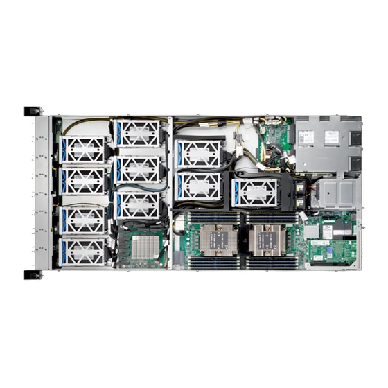
Page 9: System Board Components
Item Description LED Status Status Drive status LED Solid green Power on with no drive activity Blinking green Power on with drive activity Solid red Drive fault has occurred (refer to ID LED) Blinking red (4Hz) Drive is being located (refer to ID LED) Blinking red (1Hz) RAID rebuild in progress System board components... -
Page 10: Fan Control Board Components
Fan control board components Item Description Fan connector (J8, J9, J10, J11, J12, J13, J14, J15) Power connector (J19, J20, J21) LED board components Item Description Signal connector (J1) Component identification 10... -
Page 11: Power Interposer Board Components
Power interposer board components 12 LFF HDDs Item Description Power connector (J1) Power connector (J10) Power connector (J11) Power connector (J9) Power connector (J13) Signal connector (J17) Power connector (J5) Power connector (J6) Power connector (J4) PSU connector (J2, J3) Component identification 11... - Page 12 20 NVMe SSD Item Description Power connector (J1) Power connector (J10) Power connector (J11) Power connector (J9) Power connector (J13) Fan connector (J20) Fan connector (J19) Signal connector (J17) Power connector (J5) Power connector (J6) Power connector (J4) Power connector (J12) PSU connector (J2, J3) Component identification 12...
-
Page 13: Cpld Board Components
CPLD board components Item Description Signal connector (J2) SGPIO connector (J3) Signal connector (J12) Signal connector (J10) SGPIO connector (J5) JTAG connector (J7) Power connector (J4) SGPIO connector (J9) SGPIO connector (J6) SGPIO connector (J11) SGPIO connector (J8) Signal connector (J1) Component identification 13... -
Page 14: Cable Location
Cable Location 12 LFF HDDs 20 NVMe SSD Component identification 14... -
Page 15: Pcie Switch Board Components
PCIe switch board components Item Description Power connector (J17) SGPIO connector (J16) Slim connector (J1, J2, J3, J4, J5, J6, J7, J8, J9) Slim connector (J10) Signal connector (J11) Component identification 15... -
Page 16: Dimm Slots
DIMM slots DIMM slots are numbered sequentially (1 through 8). Use the following population order for spare replacement. Memory Module Population Rules Processor 0 DIMM Slot # 1 DIMM 2 DIMMs 3 DIMMs 4 DIMMs 5 DIMMs * 6 DIMMs 7 DIMMs * 8 DIMMs * Processor 1... -
Page 17: Dimm Label Identification
Type Ranks per DIMM DIMM Capacity (GB) Speed (MT/s); Voltage (V); Slots per and Data Width Channel (SPC) & DIMMs per Channel (DPC) DRAM Density 1 Slot per 2 Slots per Channel Channel 4 Gb 8 Gb 1 DPC 1 DPC 2 DPC 1.2 V 1.2 V... -
Page 18: Device Mapping
Item Description Status CAS latency P = CAS 15-15-15 T = CAS 17-17-17 U = CAS 20-18-18 V = CAS 19-19-19 (for RDIMM, LRDIMM) V = CAS 22-19-19 (for 3DS TSV LRDIMM) DIMM type R = RDIMM (registered) L = LRDIMM (load reduced) E = Unbuffered ECC (UDIMM) For more information about product features, specifications, options, configurations, and compatibility, see the product QuickSpecs. -
Page 19: Fan Bay Mapping
20 NVMe SSD Drive No. BIOS Port Slot 1 ~ Slot 20 SATA P0, P1 Rear Fan bay mapping 20 NVMe SSD Component identification 19... -
Page 20: Operations
Operations Power up the server To power up the server, use one of the following methods: Press the Power On/Standby button. Use Power Control function through BMC web interface. Power down the server Before powering down the server for any upgrade or maintenance procedures, perform a backup of critical server data and programs. -
Page 21: Setup
For important safety, environmental, and regulatory information, see Safety and Compliance Information for Server, Storage, Power, Networking, and Rack Products, available at the Hewlett Packard Enterprise website http://www.hpe.com/support/Safety-Compliance-EnterpriseProducts. Optimum environment When installing the server in a rack, select a location that meets the environmental standards described in this section. -
Page 22: Temperature Requirements
Temperature requirements To ensure continued safe and reliable equipment operation, install or position the system in a well-ventilated, climate-controlled environment. The maximum recommended ambient operating temperature (TMRA) for most server products is 35°C (95°F). The temperature in the room where the rack is located must not exceed 35°C (95°F). CAUTION: To reduce the risk of damage to the equipment when installing third-party options: ... -
Page 23: Rack Warnings
Connecting a DC power cable to a DC power source WARNING: To reduce the risk of electric shock or energy hazards: This equipment must be installed by trained service personnel, as defined by the NEC and IEC 60950-1, Second Edition, the standard for Safety of Information Technology Equipment. -
Page 24: Identifying The Contents Of The Server Shipping Carton
WARNING: When installing a server in a telco rack, be sure that the rack frame is adequately secured at the top and bottom to the building structure. Identifying the contents of the server shipping carton Unpack the server shipping carton and locate the materials and documentation necessary for installing the server. -
Page 25: Installing The Operating System
Procedure Press the Power On/Standby button. During the initial boot, press the Delete key in the HPE POST screen to enter the BIOS menu screen. By default, the menus are in the English language. Go to the Boot menu screen and select the desired Boot Option Priority. -
Page 26: Hardware Options Installation
Hardware options installation Introduction If more than one option is being installed, read the installation instructions for all the hardware options and identify similar steps to streamline the installation process. WARNING: To reduce the risk of personal injury from hot surfaces, allow the drives and the internal system components to cool before touching them. -
Page 27: Installing A Fan Module
Installing a fan module To install a fan module: Align the fan module with the fan bay in the chassis. Insert the fan and gently push it in until it locks in place. Redundant power supply units Removing a redundant power supply unit Hardware options installation 27... -
Page 28: Installing A Redundant Power Supply Unit
Installing a redundant power supply unit Rear solid state drives Installing a rear SSD assembly To install a rear SSD assembly: Insert the solid state drive assembly into the system. Make sure the hard drive is fully inserted. Hardware options installation 28... -
Page 29: Removing A Rear Ssd Assembly
Removing a rear SSD assembly To remove a rear SSD assembly: Grasp the solid state drive assembly and pull out of the system. Installing a rear SSD module To install a rear SSD module: Remove the rear SSD assembly (on page 29). Align the holes on the SSD bracket with the posts on the SSD. -
Page 30: Removing A Rear Ssd Module
Align the SSD in the SSD carrier, connectors facing the opening of the carrier. Install the SSD. Install the rear SSD assembly (on page 28). Removing a rear SSD module To remove a rear SSD module: Remove the rear SSD assembly (on page 29). Remove the SSD from the SSD carrier. -
Page 31: Access Panels
Remove the SSD bracket from the SSD. Access panels Removing an access panel CAUTION: Ensure that the server had been powered off and the AC power cords were disconnected from the server power supplies. To remove an access panel: Power down the server and detach all power cords from the power supplies. Loosen the thumb screw. - Page 32 Hardware options installation 32...
-
Page 33: Hard Disk Drives
Hard disk drives Removing an LFF HDD assembly To remove an LFF HDD assembly: Power down the server and detach all power cords from the power supplies. Remove the access panel (on page 31). Release the locking latches on the HDD assembly. Grasp the locking lever and lift up to slide the HDD assembly. -
Page 34: Installing An Lff Hdd Assembly
Remove the screw securing the HDD pan to the chassis. Slide the HDD pan to unlock from the chassis standoffs. Installing an LFF HDD assembly To install an LFF HDD assembly: Power down the server and detach all power cords from the power supplies. Remove the access panel (on page 31). - Page 35 Make sure the locking lever is in the open position before continuing. Align the pins on the sides of the pan with the HDD assembly. The pins slide into the carrier when they are seated correctly. Press the locking lever down to slide the HDD assembly in place. The HDD carrier is seated properly when the locking lever is completely lowered in place.
-
Page 36: Removing A 2 Lff Hdd Assembly
Removing a 2 LFF HDD assembly To remove a 2 LFF HDD assembly: Power down the server and detach all power cords from the power supplies. Remove the access panel (on page 31). Pull out the plunger on the HDD pan. Grasp the handle and lift it up until the pins on the HDD pan (x4) reach the top of the guide column. - Page 37 Release the locking latches on the HDD assembly. Grasp the locking lever on the HDD carrier and lift up to 45° angle. Do not exceed 45° to prevent damaging the mechanism. The HDD carrier slides to the open position. By extending the locking lever, the HDD carrier is unlocked and ready for installation of HDD modules.
-
Page 38: Installing A 2 Lff Hdd Assembly
Installing a 2 LFF HDD assembly To install a 2 LFF HDD assembly: Power down the server and detach all power cords from the power supplies. Remove the access panel (on page 31). Lift the locking lever and place it on the open position (45°). Align the HDD assembly in the HDD pan. - Page 39 Pull out the plunger on the HDD pan to unlock the pan. Hold the handle and move the HDD pan as illustrated in the following figure. Make sure the guide pin on the HDD carrier is clear of the locking position on the HDD pan. Continue to hold the handle and lower the HDD pan until it is sitting on the chassis.
-
Page 40: Removing An Sff Hdd Assembly
Removing an SFF HDD assembly To remove an SFF HDD assembly: Power down the server and detach all power cords from the power supplies. Remove the access panel (on page 31). Remove the power and data cables from the HDD assembly. Flip up the handle to release the HDD cage. -
Page 41: Installing An Sff Hdd Assembly
Installing an SFF HDD assembly To install an SFF HDD assembly: Power down the server and detach all power cords from the power supplies. Remove the access panel (on page 31). Install the HDD assembly into the HDD cage. Press the HDD cage down into the chassis. Flip down the handle to lock the HDD cage in the chassis. -
Page 42: Removing A 3.5" Hdd Module
Removing a 3.5” HDD module To remove a 3.5” HDD module: Power down the server and detach all power cords from the power supplies. Remove the access panel (on page 31). Remove the HDD assembly (on page 36). Remove the screws securing the HDD to the HDD carrier. Slide to remove the HDD from the HDD carrier. -
Page 43: Installing A 3.5" Hdd Module
Installing a 3.5” HDD module To install a 3.5” HDD module: Power down the server and detach all power cords from the power supplies. Remove the access panel (on page 31). Position the HDD connectors so that they face the connectors on the chassis ensuring a correct alignment. -
Page 44: Removing An Ssd Module
Removing an SSD module To remove an SSD module: Power down the server and detach all power cords from the power supplies. Remove the access panel (on page 31). Remove the SSD assembly (on page 40). Pry open the SSD bracket and remove the SSD. Hardware options installation 44... -
Page 45: Installing An Ssd Module
Installing an SSD module To install an SSD module: Power down the server and detach all power cords from the power supplies. Remove the access panel (on page 31). Pry open the SSD bracket and align the screw holes on the SSD with the pins on the SSD bracket. The connector faces the rear of the SSD bracket. -
Page 46: Fan Control Boards
Fan control boards Removing a fan control board To remove a fan control board: Power down the server and detach all power cords from the power supplies. Remove the fan modules (on page 26). Remove the access panel (on page 31). Disconnect the cables from the fan control board, see page or 90. -
Page 47: Installing A Fan Control Board
Installing a fan control board To install a fan control board: Align the holes on the fan control board with the holes on the chassis. Secure the fan control board to the chassis with screws. Connect the cables to the fan control board, see page or 90. -
Page 48: Air Baffles
Air baffles Removing an air baffle CAUTION: To avoid damaging server components, do not use force when removing the air baffle. To remove an air baffle: Power down the server and detach all power cords from the power supplies. Remove the access panel (on page 31). Remove the screws securing the air baffle and the chassis. -
Page 49: Installing An Air Baffle
Installing an air baffle CAUTION: To avoid damaging server components, do not use force when removing the air baffle. Be sure all DIMM latches are locked to avoid damaging the components. To install an air baffle: To position the air baffle, see the following figure. Lower the air baffle in the chassis. -
Page 50: Air Fences
Air fences This section applies to 20 NVMe SSD model only. Removing an air fence CAUTION: To avoid damaging server components, do not use force when removing the air fence. To remove an air fence: Power down the server and detach all power cords from the power supplies. Remove the access panel (on page 31). -
Page 51: Installing An Air Fence
Installing an air fence CAUTION: To avoid damaging server components, do not use force when installing the air fence. To install an air fence: To position the air fence, see the following figure. Lower the air fence in the chassis. Make sure the end of the air fence is locked in place on the chassis mid-wall and the hole on the air fence is locked with the post on the chassis. -
Page 52: Power Interposer Boards
Power interposer boards Removing a power interposer board To remove a power interposer board: Power down the server and detach all power cords from the power supplies. Remove the power supply units (on page 27). Remove the access panel (on page 31). Disconnect the cables from the power interposer board. -
Page 53: Installing A Power Interposer Board
Installing a power interposer board To install a power interposer board: Align the holes on the power interposer board with the holes on the chassis. Secure the power interposer board to the chassis with screws. Connect the cables to the power interposer board. For additional cable information see page 11. Install the access panel (on page 31). -
Page 54: Riser Boards
Riser boards Removing a riser board To remove a riser board: Power down the server and detach all power cords from the power supplies. Remove the access panel (on page 31). Remove the screw securing the riser assembly to the chassis. Grasp the riser assembly, and then gently lift a riser assembly up to remove the riser assembly from the chassis. -
Page 55: Installing A Riser Board
Installing a riser board To install a riser board: Align the screw holes on the riser board with the screw holes on the riser bracket. Secure the riser card to the riser bracket with screws. Gently insert the riser assembly into the PCIe slot on the system board. Secure the riser assembly to the chassis with a screw. -
Page 56: Internal Fan Modules
Internal fan modules This section applies to 20 NVMe SSD model only. Removing an internal fan module To remove an internal fan module: Power down the server and detach all power cords from the power supplies. Remove the access panel (on page 31). Remove the air fence (on page 50) Disconnect the cables from the power interposer board (connector J19 and J20). - Page 57 Lift the internal fan from the fan cage. Pull the self-retaining rubber rivets from the internal fan. Hardware options installation 57...
-
Page 58: Installing An Internal Fan Module
Installing an internal fan module To install an internal fan module: Push the self-retaining rubber rivets through the holes in the internal fan, verifying that they fully snap into place. Hold the internal fan at an angle and insert the guide pins on the internal fan into the guide pin holes on the fan cage. - Page 59 Align the holes on the internal fan assembly with the holes on the chassis. Secure the internal fan assembly to the chassis with screws. Connect the cables to the power interposer board (connector J19 and J20). Install the air fence (on page 51). Install the access panel (on page 31).
-
Page 60: Rear Storage Cages
Rear storage cages NOTE: The rear SSD assembly model was used for the following procedure. Differences may be present with other models. Removing a rear storage cage To remove a rear storage cage: Power off the server and detach all power cords from the power supplies. Remove the rear SSD assembly (on page 29). -
Page 61: Installing A Rear Storage Cage
Installing a rear storage cage To install a rear storage cage: Position the storage cage in the chassis. Make sure the screw holes on the storage cage are aligned with the standoffs on the chassis. Install the storage cage. To install correctly, make sure the flange on the top left side of the storage cage is seated underneath the flange of the PSU cage. -
Page 62: Cpld Boards
CPLD boards Removing a CPLD board To remove a CPLD board: Power down the server and detach all power cords from the power supplies. Remove the rear SSD assembly (on page 29). Remove the access panel (on page 31). Remove the air fence (on page 50) Remove the internal fan module (on page 56). -
Page 63: Installing A Cpld Board
Installing a CPLD board To install a CPLD board: Align the notch on the CPLD board with the post on the chassis. Slide the CPLD board to lock on the chassis, make sure the holes are aligned. Secure the CPLD board to the chassis with screws. Connect the cables to the CPLD board. -
Page 64: Led Boards
LED boards Removing a LED board To remove a LED board: Power down the server and detach all power cords from the power supplies. Remove the rear SSD assembly (on page 29). Remove the access panel (on page 31). Remove the air fence (on page 50) Remove the internal fan module (on page 56). -
Page 65: Installing A Led Board
Installing a LED board To install a LED board: Align the LEDs on the LED board with the holes on the chassis. Secure the LED board to the chassis with screws. Connect the cable to the LED board. For additional cable information see page 10. Install the CPLD board (on page 63). -
Page 66: Ocp Mezzanine Cards
OCP mezzanine cards Removing an OCP mezzanine card To remove an OCP mezzanine card: Power down the server and detach all power cords from the power supplies. Remove the access panel (on page 31). Remove the screws securing the OCP mezzanine card to the system board. Remove the OCP mezzanine card. -
Page 67: Installing An Ocp Mezzanine Card
Installing an OCP mezzanine card To install an OCP mezzanine card: Align the connector on the OCP mezzanine card with the slot on the system board. Install the OCP mezzanine card gently. Secure the OCP mezzanine card to the chassis with screws. Install the access panel (on page 31). -
Page 68: Pcie Switch Boards
PCIe switch boards This section applies to 20 NVMe SSD model only. Removing a PCIe switch board To remove a PCIe switch board: Power down the server and detach all power cords from the power supplies. Remove the access panel (on page 31). Disconnect the cables from the PCIe switch board. -
Page 69: Installing A Pcie Switch Board
Installing a PCIe switch board To install a PCIe switch board: Align the connector on the PCIe switch board with the slot on the system board. Make sure the notch on the PCIe switch board is locked with the post on the chassis. Install the PCIe switch board gently. -
Page 70: Nvme M.2 Cards
NVMe M.2 cards Removing a NVMe M.2 card To remove an NVMe M.2 card: Power down the server and detach all of the power cords from the power supplies. Remove the access panel (on page 31). Remove the riser board (on page 54). Remove the screw securing the NVMe M.2 card. -
Page 71: Installing A Nvme M.2 Card
Installing a NVMe M.2 card To install a NVMe M.2 card: Align the protrusion on the connector with the indentation on the NVMe M.2 card. Insert the NVMe M.2 card and lower it in place. Secure the NVMe M.2 card to the system board with the screw. Install the riser board (on page 55). -
Page 72: Trusted Platform Modules (Tpm)
Trusted Platform Modules (TPM) Removing a To remove a TPM: Power down the server and detach all of the power cords from the power supplies. Remove the access panel (on page 31). Remove the riser board (on page 54). Hold the TPM by it edges and lift the TPM from the system board gently. Hardware options installation 72... -
Page 73: Installing A Tpm
Installing a To install a TPM: Align the connector on the TPM with the connector on the system board. Insert the TPM into the connector gently to prevent damaging the pins. Install the riser board (on page 55). Install the access panel (on page 31). Hardware options installation 73... -
Page 74: Memory Modules
Memory modules Removing a memory module The system board includes 16 DIMM slots (four channels per processor, each channel contains two memory slots) for the installation of DDR4 1600/1866/2133/2400/2667 MHz memory. To remove the memory module: Power down the server and detach all of the power cords from the power supplies. Remove the access panel (on page 31). -
Page 75: Installing A Memory Module
Installing a memory module The system board includes 16 DIMM slots (four channels per processor, each channel contains two memory slots) for the installation of DDR4 1600/1866/2133/2400/2667 MHz memory. To install the memory module: Pull the locking latches of the DIMM slot outwards. Place the memory module in the socket so the notch and obstruction are aligned. -
Page 76: Processors
Processors Passive heat sinks cool processors. To achieve optimal cooling performance, TIM must be installed between the processor and heat sink. The mechanical performance of the heat sink is designed to meet the requirements of Intel processors. The heat sink is necessary to maintain chipset temperature at or below temperature limits. - Page 77 Release the latch on the CPU carrier to unlock the heat sink from the CPU assembly. Processor 0 Processor 1 Release the latches on the CPU carrier to separate it from the processor. Remove the CPU carrier. Repeat the procedure for the additional processor. Hardware options installation 77...
-
Page 78: Installing A Processor
Installing a processor CAUTION: ESD protection must be worn during the procedure to avoid damaging the components. To install a processor: Align the processor on the processor tray. Align the marker (triangle) on the CPU carrier with the same marker located on the processor. The protrusions on the CPU carrier are also aligned with the indentations on the processor when properly aligned. - Page 79 Remove the TIM material protective film from the heat sink. Processor 0 Processor 1 Locate the installation markers on the heat sink and the CPU carrier. Align the respective corners. Press the heat sink to lock on the CPU carrier. If the CPU carrier does not appear level, remove it and re-install on the heat sink.
- Page 80 Remove the processor assembly from the processor tray. Processor 0 Processor 1 Align the heat sink assembly over the CPU socket. Make sure the guide pins on the socket align with the mounting holes on the CPU carrier. Lower the heat sink assembly and install in the slot. The guide pins are inserted through the mounting holes on the heat sink assembly when properly installed.
-
Page 81: System Board Modules
System board modules Removing a system board module To remove a system board module: Power down the server and detach all of the power cords from the power supplies. Remove the access panel (on page 31). Remove the air baffle (on page 48). Remove the OCP mezzanine card (on page 66). -
Page 82: Installing A System Board Module
Installing a system board module To install a system board module: Align the I/O ports on system board with the slots on the rear of the chassis. Install the system board into the chassis. Secure the system board and the chassis with thumb screw. Connect the cables to the system board, see page or 90. -
Page 83: Rackmount Rail
Rackmount rail Removing a chassis from a rack To remove a chassis: Power down the server and detach all of the power cords from the power supplies. Disconnect the cabling from the rear side of the chassis. Loosen the thumb screws securing the chassis and pull out the chassis from the rack. Pull the chassis out until the rails lock in place. -
Page 84: Installing A Chassis On A Rack
Installing a chassis on a rack To install a chassis: Install the rackmount rails (on page 86). Align the inner rail to the outer rail and slide until there is an audible sound. The rails lock in place. Press the release latches to unlock the inner rails. Continue sliding the chassis into the rack. -
Page 85: Removing Rackmount Rails
Removing rackmount rails To remove rackmount rails: Remove the chassis from the rack (on page 83). Place the chassis on a clean work space. Remove the screws securing the inner rail. Slide the inner rail backward to release and remove the inner rail. Repeat the procedures for the remaining inner rail. -
Page 86: Installing Rackmount Rails
Installing rackmount rails To install rackmount rails: Pull the inner rail out until the rail locks in place. Press the release latches to unlock the inner and outer rails. Remove the inner rail from the outer rail. Align the holes on the inner rail with the pins on the chassis. Slide the inner rail forward so that the pins are in place. -
Page 87: Powering On And Selecting Boot Options
Repeat the procedures for the remaining inner rail. Pull out the rear bracket and leave the rear latch from the outer rail. Align the rear bracket with the rack posts. Push the rear latch to lock the rear bracket on the rack posts. Align the front bracket with the rack posts. -
Page 88: Cabling
Cabling Internal system cable routing The server internal cable routing is listed in the following figure and table: 12 LFF HDDs Item Description Quantity MB power cable Power interposer board J1, J10 to system board J19, J25 (x 1) MB sideband signal cable Power interposer board J17 to system board J15 (x 1) SSD power and signal cable Rear HDD/SSD to system board J11, J14 (x 1) - Page 89 Item Description Quantity LED board power and signal LED board J1 to CPLD board J10 (x 1) cable CPLD board power cable Power interposer board J11 to CPLD board J4 (x 1) HDD 1-4 power and signal Power interposer board J4 to HDD 1-4 (x 1) cable HDD 5-8 power and signal Power interposer board J6 to HDD 5-8 (x 1)
- Page 90 20 NVMe SSD Item Description Quantity MB power cable Power interposer board J1, J10 to system board J19, J25 (x 1) MB sideband signal cable Power interposer board J17 to system board J15 (x 1) SSD power and signal cable Rear HDD/SSD to system board J3 (x 1) CPLD board signal cable Power interposer board J15 and CPLD board J2 to fan control...
- Page 91 Item Description Quantity Fan control board power cable Power interposer board J9 to fan control board J19, J20, J21 (x 1) UID LED cable System board to front/rear of chassis (x 1) PCIe switch board signal PCIe switch board J16 to CPLD board J11 (x 1) cable LED board power and signal LED board J1 to CPLD board J10 (x 1)
-
Page 92: Software And Configuration Utilities
BMC is a remote server management processor embedded on the system boards of the servers. BMC enables the monitoring and controlling of servers from remote locations. HPE BMC management is a powerful tool that provides multiple ways to configure, update, monitor, and repair servers remotely. BMC (Standard) comes preconfigured on HPE servers without an additional cost or license. -
Page 93: Logging In
Logging in To log in to the web GUI, enter the iBMC FW IP address into a web browser. An example of using the HTTP protocol is http://10.141.104.176. An example of using the encrypted HTTPS protocol is https://10.141.104.176 NOTE: Please use the label print information to access Redfish API. IPMI/Web account information is separated from Redfish account. - Page 94 Updating BMC under Linux using Yafuflash To update BMC under Linux using Yafuflash: Log into Linux. Open the terminal. Copy the BMC FW package to the /root/Desktop directory using the command: cp file_name.zip /root/Desktop Change the directory using the / root/Desktop, command: cd /root/Desktop Uncompressed the BMC FW package using the command: upzip file_name.zip...
- Page 95 Execute ./update.sh to update BMC, and wait for the BMC to update successfully. See the following figures for further information. Software and configuration utilities 95...
- Page 96 Software and configuration utilities 96...
- Page 97 Updating BMC via a web GUI To update BMC using the web GUI: Log into the web GUI using a web browser. Select Maintenance from the left tree view, and then click Firmware Update. Choose the Preserve all configuration on the checkbox if all configurations need to be preserved. Software and configuration utilities 97...
- Page 98 Select Firmware Image to select the BMC FW image. Click Start Firmware Update. Software and configuration utilities 98...
- Page 99 Choose Flash selected section (Default is all) to start BMC FW update. After BMC FW is updated, system displays a message. Software and configuration utilities 99...
-
Page 100: Hpe Pointnext Portfolio
HPE Pointnext Portfolio HPE Pointnext delivers confidence, reduces risk, and helps customers realize agility and stability. Hewlett Packard Enterprise helps customers succeed through Hybrid IT by simplifying and enriching the on-premise experience, informed by public cloud qualities and attributes. Operational Support Services enable you to choose the right service level, length of coverage, and response time to fit your business needs. -
Page 101: System Utilities
System utilities BIOS settings There are eight menus in the BIOS setup utility, which appear in the following order: Main, Advanced, Platform Configuration, Socket Configuration, Server Mgmt, Security, Boot, and Save & Exit. Use the arrow keys to navigate the menus or options that are listed on the menu. Configurable menu options or fields appear in color. - Page 102 Main screen The Main screen is the first screen that is displayed when the BIOS Setup is entered, unless an error has occurred. If an error has occurred, the Error Manager screen is displayed instead. NOTE: BIOS Information and Memory Information are dynamic string and depend on current BIOS and installed memory.
- Page 103 Setup Item Options Help Text Comments Information only. Displays the Processor Processor information. Information only. Displays the PCH information. Information only. Displays the RC Revision RC Revision information. Information only. Displays the Total Memory total physical memory installed in the system, in MB or GB. The term physical memory indicates the total memory discovered in the form of installed DIMMs.
- Page 104 Setup Item Options Help Text Comments Disable Control Wake on LAN Wake on LAN Control Enable Enable/Disable. This formset allows the user to Intel(R) Virtual RAID on manage Intel(R) Virtual RAID on CPU. Trusted Computing Settings. Trusted Computing System Super IO Chip AST2500 Super IO Parameters.
- Page 105 AST2500 Super IO Configuration The AST2500 Super IO Configuration screen allows the user to view the Super IO Chip Version and configure Serial Port. To access this screen from the Main screen, choose Advanced > AST2500 Super IO Configuration. Setup Item Options Help Text Comments...
- Page 106 COM Port (Physical) Configuration screen To access this screen from the Main screen, choose Advanced > AST2500 Super IO Configuration > COM Port (Physical) Configuration screen. Setup Item Options Help Text Comments Disabled Enable or disable COM Port. COM Port Enabled IO=3F8h;IRQ=4;...
- Page 107 COM Port (SOL) Configuration screen To access this screen from the Main screen, choose Advanced > AST2500 Super IO Configuration > COM Port (SOL) Configuration screen. Setup Item Options Help Text Comments Disabled Enable or disable COM Port COM Port Enabled IO=2F8h;...
- Page 108 Serial Port Console Redirection screen The Console Redirection screen allows the user to enable or disable console redirection and to configure the connection options for this feature. To access this screen from the Main screen, choose Advanced > Serial Port Console Redirection. NOTE: If the Console Redirection item is “Disabled”, the Console Redirection Settings item will turn gray.
- Page 109 Console Redirection Settings screen (Physical) If the Console Redirection item is “Enabled”, The Console Redirection Settings screen allows the user to configure the connection options for this feature. To access this screen from the Main screen, choose Advanced > Serial Port Console Redirection> “Console Redirection Settings”...
- Page 110 Setup Item Options Help Text Comments Stop bits indicate the end of a Stop Bits serial data packet. (A start bit indicates the beginning). The standard setting is 1 stop bit. Communication with slow devices may require more than 1 stop bit.
- Page 111 Console Redirection Settings screen (SOL) If the Console Redirection item is “Enabled”, The Console Redirection Settings screen allows the user to configure the connection options for this feature. To access this screen from the Main screen, choose Advanced > Serial Port Console Redirection > Console Redirection Settings of COM Port (SOL). Setup Item Options Help Text...
- Page 112 Setup Item Options Help Text Comments Stop bits indicate the end of a Stop Bits serial data packet. (A start bit indicates the beginning). The standard setting is 1 stop bit. Communication with slow devices may require more than 1 stop bit.
- Page 113 Legacy Console Redirection Settings To access this screen from the Main screen, choose Advanced > Serial Port Console Redirection > Legacy Console Redirection Settings. Setup Item Options Help Text Comments COM Port Select a COM port to display Legacy Serial (Physical) redirection of Legacy OS and Redirection...
- Page 114 Console Redirection Settings screen (EMS) If the EMS Console Redirection item is “Enabled”, the Console Redirection Settings screen allows the user to configure the connection options for this feature. To access this screen from the Main screen, choose Advanced > Serial Port Console Redirection> Console Redirection Settings of EMS.
- Page 115 Setup Item Options Help Text Comments None Flow control can prevent data Flow Control Hardware loss from buffer overflow. When RTS/CTS sending data, if the receiving buffers are full, a ’stop’ signal Software Xon/Xoff can be sent to stop the data flow.
- Page 116 Network Stack Configuration screen The Network Stack Configuration screen allows the user to configure the Network Stack feature. If user wants to boot to UEFI PXE, “Network Stack” should be “Enabled”. To access this screen from the Main screen, choose Advanced > Network Stack Configuration. Setup Item Options Help Text...
- Page 117 NVMe Configuration screen The NVMe Configuration screen allows the user to configure the NVMe controller options. To access this screen from the Main screen, choose Advanced > NVMe Configuration. Software and configuration utilities 117...
- Page 118 USB Configuration screen The USB Configuration screen allows the user to configure the USB controller options. To access this screen from the Main screen, choose Advanced > USB Configuration. Setup Item Options Help Text Comments Enabled Enables Legacy USB Support. Legacy USB Support Disabled AUTO option disables legacy...
- Page 119 Setup Item Options Help Text Comments Enable or disable this USB port. When “XHCI Mode” is enabled, Disabled BMC USB 2.0 Port B Enabled this item will be hided. NOTE: When XHCI Mode is enabled, BMC USB 2.0 Port A and BMC USB 2.0 Port B will be hidden, and when disabled XHCI Mode, BMC USB 2.0 Port A and BMC USB 2.0 Port B will be displayed.
- Page 120 Platform Configuration screen The Platform Configuration screen provides an access point to configure several options. On this screen, the user selects the option that is to be configured. Configurations are performed on the selected screen, and not directly on the Platform Configuration screen. To access this screen from the Main screen, press the right arrow until the Platform Configuration screen is chosen.
- Page 121 PCH Configuration screen The PCH Configuration screen allows the user to modify PCH Configuration. To access this screen from the Main screen, choose Platform Configuration > PCH Configuration. Setup Item Options Help Text Comments SATA devices and settings. PCH SATA Configuration sSATA devices and settings.
- Page 122 PCH SATA Configuration screen To access this screen from the Main screen, choose Platform Configuration > PCH Configuration > PCH SATA Configuration. Setup Item Options Help Text Comments Disable Enable or Disable SATA SATA Controller Enable Controller. AHCI Identify the SATA port is This item will be hidden when Configure SATA as set “SATA Controller”...
- Page 123 PCH sSATA Configuration screen To access this screen from the Main screen, choose Platform Configuration > PCH Configuration > PCH sSATA Configuration. Setup Item Options Help Text Comments Disable Enable or Disable SATA sSATA Controller Enable Controller. AHCI Identify the SATA port is This item will be hidden when Configure sSATA as set “sSATA Controller”...
- Page 124 Server ME Configuration screen The Server ME Configuration screen allows the user to modify Server ME Configuration. To access this screen from the Main screen, choose Platform Configuration > Server ME Configuration. Setup Item Options Help Text Comments Information only. Oper.
- Page 125 Setup Item Options Help Text Comments Information only. Error Code Information only. Recovery Cause 8000 The altitude of the platform Altitude location above sea level expressed in meters. The hex number is decoded as 2's complement signed integer. Information only. ME Firmware Features Information only.
- Page 126 Processor Configuration screen The Processor Configuration screen allows the user to configure Processor. To access this screen from the Main screen, choose Socket Configuration > Processor Configuration. Setup Item Options Help Text Comments Change Per-Socket Settings. Per-Socket Configuration Information only. Processor BSP Revision Information only.
- Page 127 Setup Item Options Help Text Comments Information only. Displays Processor ID current used Processor ID. Information only. Displays Processor Frequency current used Processor frequency. Information only. Displays Processor Max Ratio current used Processor max ratio. Information only. Displays Processor Min Ratio current used Processor min ratio.
- Page 128 Setup Item Options Help Text Comments 32KB 8Way MSR 31h Bit[0] - A write of 1 DCU Mode Without ECC selects the DCU mode as 16KB 16KB 4Way With 4-way with ECC. Disable Enable/Disable AES-NI support. AES-NI Enable Per-Socket Configuration screen To access this screen from the Main screen, choose Socket Configuration >...
- Page 129 CPU Socket 0 Configuration screen To access this screen from the Main screen, choose Socket Configuration > Processor Configuration > Per-Socket Configuration > CPU Socket 0 Configuration. Setup Item Options Help Text Comments 0: Enable all cores. FFFFFF: Cores Disable Bitmap Disable all cores.
- Page 130 CPU Socket 1 Configuration screen To access this screen from the Main screen, choose Socket Configuration > Processor Configuration > Per-Socket Configuration > CPU Socket 1 Configuration. Setup Item Options Help Text Comments 0: Enable all cores. FFFFFF: Cores Disable Bitmap Disable all cores.
- Page 131 Common RefCode Configuration screen The Common RefCode Configuration screen allows the user to modify Common RefCode Configuration. To access this screen from the Main screen, choose Socket Configuration > Common RefCode Configuration. Setup Item Options Help Text Comments Disable Isoc: Disable, Enable. Isoc Mode Enable Auto...
- Page 132 UPI Configuration screen The UPI Configuration screen allows the user to modify UPI Configuration. To access this screen from the Main screen, choose Socket Configuration > UPI Configuration. Setup Item Options Help Text Comments Displays and provides option to UPI General change the UPI General Configuration Settings.
- Page 133 UPI General Configuration screen To access this screen from the Main screen, choose Socket Configuration > UPI Configuration > UPI General Configuration. Setup Item Options Help Text Comments UPI status Help. UPI Status Slow Select the UPI link speed as Link Speed Mode Fast either the POR speed (Fast) or...
- Page 134 Setup Item Options Help Text Comments Disable XPT Prefetch. XPT Prefetch Enable Disable KTI Prefetch. KTI Prefetch Enable Disable Local/Remote Threshold setting. Local/Remote Auto Threshold Medium High Disable Stale A to S Dir optimization. Stale AtoS Enable Auto Enable – opportunistically fill Disable LLC dead line alloc dead lines in LLC.
- Page 135 Setup Item Options Help Text Comments Information only. UPI Global MMIO High Base / Limit Information only. UPI PCI-E Configuration Base / Size UPI Dfx Configuration To access this screen from the Main screen, choose Socket Configuration > UPI Configuration > UPI General Configuration.
- Page 136 Memory Configuration screen The Memory Configuration screen allows the user to modify Memory Configuration. To access this screen from the Main screen, choose Socket Configuration > Memory Configuration. Setup Item Options Help Text Comments Auto Maximum Memory Frequency Memory Frequency 1600 Selections in Mhz.
- Page 137 Memory Topology screen To access this screen from the Main screen, choose Socket Configuration > Memory Configuration > Memory Topology. Setup Item Options Help Text Comments Information only. Displays SX.ChX.DX Current memory information on board. Software and configuration utilities 137...
- Page 138 Page Policy To access this screen from the Main screen, choose Socket Configuration > Memory Configuration > Page Policy. Setup Item Options Help Text Comments Auto Select Page Policy. Page Policy Closed Adaptive Software and configuration utilities 138...
- Page 139 Memory Map screen To access this screen from the Main screen, choose Socket Configuration > Memory Configuration > Memory Map. Setup Item Options Help Text Comments Selects whether 1LM or 2LM Volatile Memory Mode memory mode should be Auto enabled. Auto Select IMC Interleaving setting.
- Page 140 Memory RAS Configuration screen To access this screen from the Main screen, choose Socket Configuration > Memory Configuration > Memory RAS Configuration. Setup Item Options Help Text Comments Disable Enable Static Virtual Lockstep Static Virtual Lockstep Enable mode. Mode Disable Mirror Mode will set entire Mirror mode Mirror Mode 1LM...
- Page 141 IIO Configuration screen The IIO Configuration screen allows the user to modify IIO Configuration. To access this screen from the Main screen, choose Socket Configuration > IIO Configuration. Setup Item Options Help Text Comments Socket0 Configuration All IOAT configuration options. IOAT Configuration Press <Enter>...
- Page 142 Socket0 Configuration screen To access this screen from the Main screen, choose Socket Configuration > IIO Configuration > Socket0 Configuration. Setup Item Options Help Text Comments x4x4x4x4 Selects PCIe port Bifurcation for IOU0 (IIO PCIe Br1) x4x4x8 selected slot(s). x8x4x4 x8x8 Auto Settings related to PCI Express...
- Page 143 Socket 0 PcieBr1D00F0 – Port 1A screen To access this screen from the Main screen, choose Socket Configuration > IIO Configuration > IIO0 Configuration > Socket 0 PcieBr1D00F0 – Port 1A. Setup Item Options Help Text Comments Auto In auto mode the BIOS will PCI-E Port Disable remove the EXP port if there is...
- Page 144 Socket 0 PcieBr2D00F0 – Port 2A screen To access this screen from the Main screen, choose Socket Configuration > IIO Configuration > IIO0 Configuration > Socket 0 PcieBr2D00F0 – Port 2A. Setup Item Options Help Text Comments Auto In auto mode the BIOS will PCI-E Port Disable remove the EXP port if there is...
- Page 145 IOAT Configuration screen To access this screen from the Main screen, choose Socket Configuration > IIO Configuration > IOAT Configuration. Setup Item Options Help Text Comments TLP Processing Hint disable. Disable TPH Enable Prioritize TPH. This item will be hidden if Prioritize TPH “Disable TPH”...
- Page 146 Intel® VT for Directed I/O (VT-d) screen To access this screen from the Main screen, choose Socket Configuration > IIO Configuration > Intel® VT for Directed I/O (VT-d). Setup Item Options Help Text Comments Enable Enable/Disable Intel® Intel® VT for Directed Disable Virtualization Technology for I/O (VT-d)
- Page 147 Advanced Power Management Configuration screen The Advanced Power Management Configuration screen allows the user to configure Advanced Power Management. To access this screen from the Main screen, choose Socket Configuration> Advanced Power Management Configuration. Setup Item Options Help Text Comments P State Control Configuration CPU P State Control Sub Menu, include Turbo, XE...
- Page 148 CPU P State Control screen To access this screen from the Main screen, choose Socket Configuration > Advanced Power Management Configuration > CPU P State Control. Setup Item Options Help Text Comments Disable Enable/Disable EIST (P-States). SpeedStep (Pstates) Enable HW_ALL Choose This item will turn to gray if EIST PSD Function...
- Page 149 Hardware PM State Control To access this screen from the Main screen, choose Socket Configuration > Advanced Power Management Configuration > Hardware PM State Control. Setup Item Options Help Text Comments Disable Disable: Hardware chooses a Hardware P-States Native Mode P-state based on OS Request Out of Band Mode (Legacy P-States).
- Page 150 CPU C State Control screen To access this screen from the Main screen, choose Socket Configuration > Advanced Power Management Configuration > CPU C State Control. Setup Item Options Help Text Comments Disable Enable/Disable CPU C6 (ACPI CPU C6 Report Enable C3) report to OS.
- Page 151 Package C State Control screen To access this screen from the Main screen, choose Socket Configuration > Advanced Power Management Configuration > Package C State Control. Setup Item Options Help Text Comments C0/C1 State Package C State limit CPU C6 Report C2 state C6 (non Retention) state...
- Page 152 CPU – Advanced PM Tuning screen To access this screen from the Main screen, choose Socket Configuration > Advanced Power Management Configuration > CPU - Advanced PM Tuning. Setup Item Options Help Text Comments Energy Perf BIAS Sub Menu. Energy Perf BIAS Enable MSR 1FCh Bit [22] = SAPM Control...
- Page 153 Energy Perf BIAS screen To access this screen from the Main screen, choose Socket Configuration > Advanced Power Management Configuration > CPU - Advanced PM Tuning > Energy Perf BIAS. Setup Item Options Help Text Comments OS Controls EPB MSR 1FCh Bit [25] = Power Performance BIOS Controls PWR_PERF_TUNING_CFG_M...
- Page 154 Setup Item Options Help Text Comments The HW switching mechanism DISABLES the performance TotalTimeThreshold setting (0) when the total P0 time is less than this threshold. The HW switching mechanism ENABLES the performance TotalTimeThreshold setting (0) when the total P0 High time is greater than this threshold.
- Page 155 Setup Item Options Help Text Comments Disable Enable/Disable PL2. If this PL2 Limit Enable option is disabled, BIOS will program the deafult values for PL2 Power Limit and PL2 Time Window. PL2 Power Limit in Watts. The This item will be hidden when PL2 Power Limit “PL2 Limit”...
- Page 156 Server Mgmt screen The Server Mgmt screen displays the information of BMC. To access this screen from the Main screen, choose Server Mgmt. Setup Item Options Help Text Comments Information only. BMC Self Test Status Information only. BMC Device ID Information only.
- Page 157 Setup Item Options Help Text Comments Do Nothing Configure how the system FRB-2 Timer Policy Reset should respond if the FRB-2 Power Down Timer expires. Not available if Power Cycle FRB-2 Timer is disabled. Enabled If enabled, starts a BIOS timer OS Watchdog Timer Disabled which can only be shut off by...
- Page 158 System Event Log screen The System Event Log screen displays the configuration of System Event Log. To access this screen from the Main screen, choose Server Mgmt > System Event Log. Setup Item Options Help Text Comments Disabled Change this to enable or disable SEL Components Enabled all features of System Event...
- Page 159 View FRU information The View FRU information screen displays the FRU information. To access this screen from the Main screen, choose Server Mgmt > View FRU information. Setup Item Options Help Text Comments Information Only. System Manufacturer Information Only. System Product Name Information Only.
- Page 160 Setup Item Options Help Text Comments Information Only. SDR Version Information Only. System UUID NOTE: No FRU information for fields indicate. BMC network configuration screen The BMC Network Configuration screen displays the information of LAN channel. To access this screen from the Main screen, choose Server Mgmt >...
- Page 161 Setup Item Options Help Text Comments Unspecified Select to configure LAN channel During BIOS phase, BIOS will Configuration Address Static parameters statically or send IPMI command to change Source DynamicBmcDhcp dynamically (by BIOS or BMC). BMC network IP source to this An unspecified option does not item specified, after that, this item’s value will revert back to...
- Page 162 Setup Item Options Help Text Comments Information only. Displays the Station MAC address Station MAC Address get from BMC. Information only. Displays the Router IP Address Router IP Address get from BMC. Information only. Displays the Router MAC Address Router MAC Address get from BMC.
- Page 163 Setup Item Options Help Text Comments Unspecified Select to configure LAN channel Configuration Address Static parameters statically or Source DynamicBmcDhcp dynamically (by BIOS or BMC). Unspecified option will not modify any BMC network parameters during BIOS phase. Information only. Current Configuration Address source Information only.
- Page 164 Setup Help Text Comments Item TIME SENSOR TYPE Information only. DATE HH:MM:SS IPMI 2.0 16 bytes SEL Log data and Describe SEL logs follow IPMI MM/DD/YY specified related description. 2.0 Specification. sensor type Security screen The Security screen allows the user to enable and set the user and administrative password. This action locks out the front panel buttons preventing further access.
- Page 165 Secure Boot Screen To access this screen from the Main screen, choose Security > Secure Boot. Setup Item Options Help Text Comments Setup System Mode Not Active Secure Boot Not Active Vendor Keys Disabled Secure Boot activated when This item turns gray when Boot Attempt Secure Boot Enabled Platform Key(PK) is enabled,...
- Page 166 Key management screen To access this screen from the Main screen, choose Security > Secure Boot > Key Management. Setup Item Options Help Text Comments Disabled Allows user to provision factory Provision Factory Enabled default Secure Boot keys when System is in Setup Mode If “Provision Factory Defaults”...
- Page 167 Setup Item Options Help Text Comments If “Provision Factory Defaults” Set New Enroll Factory Defaults or load Platform Key(PK) | 0 | set to “Enabled” or “Install the keys from a file with: 0| No Key Factory Default keys” is 1.
- Page 168 Setup Item Options Help Text Comments If “Provision Factory Defaults” Set New Enroll Factory Defaults or load Forbidden Signatures| set to “Enabled” or “Install Append the keys from a file with: 0 | 0| No Key Factory Default keys” is 1.
- Page 169 Boot screen The Boot screen displays any bootable media encountered during POST, and allows the user to configure desired boot device. To access this screen from the Main screen, choose Boot. Setup Item Options Help Text Comments Setup Prompt Timeout 3 Number of seconds to wait for setup activation key.
- Page 170 Setup Item Options Help Text Comments Hard Disk Sets the system boot order. If there is another bootable Boot Option #2 NVME device present, it will be in the CD/DVD option list. USB Devices Network UEFI AP:UEFI: Built-in EFI Shell Hard Disk Sets the system boot order If there is another bootable...
- Page 171 Save & Exit screen The Save & Exit screen allows the user to choose whether to save or discard the configuration changes made on the other screens. It also allows the user to restore the server to the factory defaults. If Load Default Values is selected, the factory default settings (NOTE in bold in the tables in this chapter) are applied.
-
Page 172: Event Logging
Event logging One of the major requirements of server management is to correctly and consistently log and handle critical system events. System events contain: Events and errors detected during POST Errors detected during runtime Events and errors detected during POST There two methods to treat the events/errors detected during POST: ... - Page 173 Error detected during runtime Memory error log The BIOS support runtime memory ECC error detection and log. With ECC in operation, in the process of every fetch from memory, the data and ECC bits are examined for each 64-bit data + 8-bit ECC group. If the ECC computation indicates that a single bit Correctable Error (CE) has occurred, it is corrected and the corrected data is passed on to the processor.
- Page 174 PCIe Error Log The BIOS support runtime PCIE correctable, uncorrectable non-fatal and uncorrectable fatal error detection and log. PCIe Error Log Sensor Name Generic SEL Value Description Info 0x02 System Event Record Record Type 0x0021 Generated by SMI Handler Generator ID 0x13 PCIe Sensor Type Sensor Type...
- Page 175 CPU error log The BIOS provides correctable CPU configuration, uncorrectable and fatal error detection and logs. CPU Error Log Processor Sensor Name Generic SEL Value Description Info 0x02 System Event Record Record Type 0x0021 Generated by SMI Handler Generator ID 0x07 Processor Sensor Type Sensor Type...
- Page 176 BIOS boot up log The BIOS support bios boot up detection and log. BIOS Boot Up Log BIOS Boot Up Sensor Name Generic SEL Value Description Info 0x02 System Event Record Record Type 0x0001 Generated by BIOS Generator ID 0x1D Sensor Type 0xA5 BMC define...
-
Page 177: Entering The Pop-Up Boot Menu
Byte Field Description Generator ID RqSA & LUN if event was generated from IPMB. Software ID if 8 : 9 event was generated from system software. Byte 1 [7:1] - 7-bit I C . Slave Address, or 7-bit system software ID [0] 0b = ID is IPMB Slave Address 1b = system software ID Byte 2... -
Page 178: Bios Maintenance
Use the left and right arrow keys to navigate the different menu options. When a menu option is selected, the top-level screen for that option appears. Use the up and down arrow keys to scroll up and down to select an item on a top-level screen. When the up and down arrow keys are pressed, the only options that are highlighted are the options that can be modified. - Page 179 The password length must be in the following range: Minimum length: 3 Maximum length: 20 Password Logic Administrator User Password Boot to OS ESC/DEL to Enter BIOS Password Setup No password required No password required Password required Password required No password required Password required Password required...
-
Page 180: Checking The Fw Version
BIOS jumpers This section provides information about the BIOS. See the following table to locate the BIOS maintenance jumpers. Item Parameter Silk-screen Function Description ME RECOVERY MODE Recovery ME CMOS CLEAR JUMPER Clear CMOS BMC Reset Reset BMC BMC force update jumper Force BMC update Flash security override Enable/disable flash security override... -
Page 181: Checking The Bios Version Using The Bios Setup Utility
Checking the BIOS version using the BIOS setup utility Log into the BIOS setup utility. Use the arrow keys to select the Main to display the BIOS version as shown in the following figure. Checking the BMC version using Linux Log into Linux. -
Page 182: Checking The Bmc Version Using The Web Gui
Checking the BMC version using the web GUI Log into the web GUI. Select Maintenance from the left tree view, and then click Firmware Information to display the BMC version, as shown in the following figure. Checking the event log Checking the system event log using Linux remote desktop To check the system event log using LinuxLog into Linux. -
Page 183: Checking The System Event Log Using The Web Gui
Checking the system event log using the web GUI To check the system event log using the web user interface: Log into the web GUI. Select Dashboard from the left tree view, and then click Firmware Information. Click Details link on Today and 30 days to display the system event log. Software and configuration utilities 183... -
Page 184: Checking The Event Log Using The Bios Setup Utility
Checking the event log using the BIOS setup utility To check the event log using the BIOS setup utility: Enter the BIOS setup utility, and then select the Server Mgmt menu. Software and configuration utilities 184... - Page 185 Use the arrow keys to select View System Event Log, and then press Enter. The “System Event Log” displays. Software and configuration utilities 185...
-
Page 186: Illustrated Parts Catalog
Illustrated parts catalog System components Hewlett Packard Enterprise continually improves and changes product parts. For complete and current supported parts information, see the Hewlett Packard Enterprise PartSurfer website: http://www.hpe.com/info/partssurfer 12 LFF HDDs Illustrated parts catalog 186... - Page 187 Item Description Spare part number Customer self repair (on page 225) Access panel Mandatory 3.5” HDD (10) Mandatory 3.5” HDD (2) Mandatory 2.5” HDD/SSD (2) Mandatory Hot-swappable fan (8) P04881-001 Mandatory Air baffle Mandatory Fan control board P04887-001 Mandatory 1U chassis Mandatory CPLD board P04879-001...
- Page 188 20 NVMe SSD Item Description Spare Part Number Customer self repair (on page 225) Access panel Mandatory Air fence Mandatory 2.5” HDD/SSD (20) Mandatory Internal fan (2) Mandatory P04882-001 PCIe switch board Mandatory P04891-001 2.5” HDD/SSD (2) Mandatory Hot-swappable fan (8) Mandatory P04881-001 Illustrated parts catalog 188...
- Page 189 Mandatory HPE CL Cbl CPLD signal board P04894-001 Mandatory HPE CL Cbl MB Sideband Signal P04894-001 Mandatory HPE CL Cbl 2xSSD Pwr Signal MB SATA to SSD P04898-001 P11100-001 Mandatory CBL, CL3100 Gen10 HDD 5-8 RAID extension P11100-001 Mandatory CBL, CL3100 Gen10 HDD 9-12 RAID extension...
- Page 190 HPE CL Cbl PCIe switch board power P04897-001 Mandatory HPE CL Cbl PCIe switch board signal P04897-001 Mandatory HPE CL Cbl 2xSSD Pwr Signal MB Hd to SSD P04898-001 Mandatory HPE CL4100 G4 Proc 1 Heat Sink 882233-001 Mandatory HPE CL4100 G4 Proc 2 Heat Sink...
-
Page 191: Troubleshooting
Troubleshooting Troubleshooting preparation Pre-diagnostic WARNING: To avoid potential problems, ALWAYS read the warnings and cautionary information in the server documentation before removing, replacing, reseating or modifying system components. IMPORTANT: Refer to the server documentation for information on procedures, hardware options, software tools and operating systems supported by the server. Follow the following pre-diagnostic steps before system troubleshooting process: Review the important safety information. -
Page 192: Prepare The Server For Diagnosis
Always locate the documentation for your installed processor model before performing any steps that require installing, removing, or replacing a processor. If you cannot locate the hard copy of the instructions, locate the server user and maintenance guide in the HPE Enterprise Information Library (www.hpe.com/info/EIL). -
Page 193: Disassembling The Server Down To The Minimum Hardware Configuration
Disassembling the server down to the minimum hardware configuration During the troubleshooting process, it might be necessary to setup the server to the minimum hardware configuration. A minimum configuration consists of only the components needed to boot the server and successfully complete POST. -
Page 194: Battery Replacement
Battery replacement If the server no longer automatically displays the correct date and time, you might need to replace the battery that provides power to the real-time clock. WARNING: The computer contains an internal lithium manganese dioxide, a vanadium pent oxide, or an alkaline battery pack. -
Page 195: Electrostatic Discharge
Electrostatic discharge Preventing electrostatic discharge To prevent damaging the system, be aware of the precautions you must follow when setting up the system or handling parts. A discharge of static electricity from a finger or other conductor may damage system boards or other static-sensitive devices. This type of damage may reduce the life expectancy of the device. -
Page 196: Specifications
Specifications Environmental specifications Specification Value — Temperature range* 10°C to 35°C (50°F to 95°F) Operating -30°C to 60°C (-22°F to 140°F) Non-operating — Relative humidity (Non-condensing) Minimum to be the higher (more moisture) of -12°C (10.4°F) dew Operating point or 8% relative humidity Maximum to be 28°C (82.4°F) dew point or 90% relative humidity ... - Page 197 Physical media distribution might require a fee to cover the media and mailing costs. Accessing Hewlett Packard Enterprise Support • For live assistance, go to the Contact Hewlett Packard Enterprise Worldwide website: http://www.hpe.com/assistance • To access documentation and support services, go to the Hewlett Packard Enterprise Support Center website: http://www.hpe.com/support/hpesc Information to collect •...
- Page 198 HPE Cloudline Support Services HPE Packaged Support Services Created for service providers, HPE Cloudline Support Services are a selection of hardware support features designed to help keep your IT staff focused on your business, not on repair and maintenance activities.
- Page 199 Regulatory information To view the regulatory information for your product, view the Safety and Compliance Information for Server, Storage, Power, Networking, and Rack Products, available at the Hewlett Packard Enterprise Support Center: www.hpe.com/support/Safety-Compliance-EnterpriseProducts Belarus Kazakhstan Russia marking Manufacturer and Local Representative Information Manufacturer information: Hewlett Packard Enterprise Company, 3000 Hanover Street, Palo Alto, CA 94304 U.S.
- Page 200 Turkey RoHS material content declaration Ukraine RoHS material content declaration Support and other resources 200...
- Page 201 Hewlett Packard Enterprise is committed to providing documentation that meets your needs. To help us improve the documentation, send any errors, suggestions, or comments to Documentation Feedback (mailto:docsfeedback@hpe.com). When submitting your feedback, include the document title, part number, edition, and publication date located on the front cover of the document. For online help content, include the product name, product version, help edition, and publication date located on the legal notices page.
Need help?
Do you have a question about the Cloudline CL3100 Gen10 and is the answer not in the manual?
Questions and answers