Sign In
Upload
Manuals
Brands
Teledyne Manuals
Digital Camera
NIRvana System
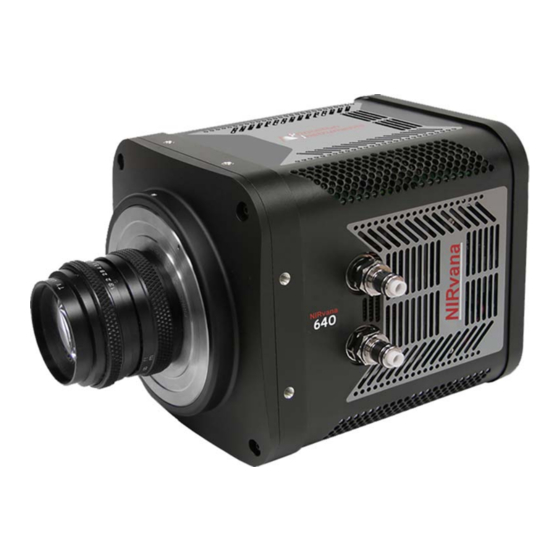
Teledyne NIRvana System Manuals
Manuals and User Guides for Teledyne NIRvana System. We have
1
Teledyne NIRvana System manual available for free PDF download: Manual
Teledyne NIRvana System Manual (126 pages)
Brand:
Teledyne
| Category:
Digital Camera
| Size: 4.68 MB
Table of Contents
Table of Contents
3
Chapter 1: About this Document
9
Intended Audience
9
Related Documentation
9
Table 1-1: Related Documentation
9
Document Organization
10
Conventions Used in this Manual
11
Safety Information
12
Safety Related Symbols Used in this Manual
12
Precautions
13
Chapter 2: Nirvana Camera System
15
Figure 2-1: Nirvana Camera System: Standard Items
15
Figure
15
Nirvana Camera
16
Figure 2-2: Typical Nirvana Camera
16
CCD Sensor
17
Cooling
17
Internal Fan
18
External Coolant Circulator
18
Window
17
Figure 2-3: Nirvana Rear-Panel Connectors
19
Rear-Panel Connectors
19
Table 2-1: Nirvana Rear-Panel Connectors
19
Standard Cables
20
Table 2-2: Standard Nirvana Camera System Cables
20
Coolant Hoses
21
Certificate of Performance
21
Nirvana System User Manual
21
Table 2-3: Coolant Hose and Fitting Information
21
Optional Accessories
22
Application Software
22
Coolant Circulator
23
Optical Adapters
24
Care and Cleaning of a Nirvana System
24
Detector Window
24
Cleaning
24
Camera
24
Optical Surfaces
24
Figure 2-4: Optional Optical Adapters
24
Repairs
25
Chapter 3 Installation
27
Table 3-1: Nirvana System Installation Procedure
27
Figure 3-1: Typical Imaging Experiment Layout: Air-Cooled Camera
28
Figure 3-2: Typical Spectroscopy Experiment Layout: Air-Cooled Camera
29
Figure 3-3: Typical Imaging Experiment Layout: Air/Liquid-Cooled Camera
29
Camera
30
Figure 3-4: Typical Spectroscopy Experiment Layout: Air/Liquid-Cooled
30
Chapter 4 System Setup
31
Unpacking the System
31
Checking the Equipment and Parts Inventory
32
System Requirements
33
Environmental Requirements
33
Camera Ventilation
33
Power Requirements
33
Host Computer Specifications
34
Winx Host Computer Requirements
34
Lightfield Host Computer Requirements
35
Data Acquisition Software Installation
36
Installing Lightfield
36
Figure 4-1: Typical Lightfield Installation Wizard Dialog
36
Installing Winx
37
Figure 4-2: Typical Winview/32 Setup Dialog
37
Attaching a Lens to a C-Mount Adapter
38
Mounting the Lens
38
Adjusting a C-Mount Adapter
39
Figure 4-3: Adjustable C-Mount Adapter
39
Making the Camera-Circulator Connections for a Coolcubeii
40
Configure Default Lightfield Camera Parameters
42
Figure 4-4: Typical Lightfield Experiment Workspace
42
Chapter 5 Operation
43
Figure 5-1: Nirvana Light Path Diagram
43
Winx On/Off Sequences
44
Chapter 6: Lightfield First Light Procedure
45
Imaging Applications
45
Configure Lightfield
45
Figure 6-1: Typical Available Devices Area
46
Figure 6-2: Typical Experiment Devices Area with Nirvana Camera
46
Acquire Data
47
Typical View Area
47
Figure 6-4: Typical View Area Displaying an Image
47
Shut down Procedure
48
Spectroscopy Applications
49
Configure Lightfield
49
Figure 6-5: Available Devices Area
50
Verify the Setup
51
Figure 6-6: Experiment Devices Area
51
Rotational Alignment and Focus
52
Rotational Alignment
53
Typical View Area
53
Figure 6-8: Alignment Spectrometer: Pre-Rotational Alignment
54
Figure 6-9: Alignment Spectrometer: Post Rotational Alignment
55
Focus
55
Acquire Data
56
Shut down Procedure
56
Chapter 7: Winx First Light Procedure
57
Imaging Applications
57
Configure Winview/32
57
Figure 7-1: Typical Hardware Setup Dialog: Controller/Camera Tab
58
Figure 7-2: Typical Detector Temperature Dialog
59
Figure 7-3: Typical Experiment Setup
59
Timing Tab
59
Verify the Setup
60
Shut down Procedure
60
Spectroscopy Applications
61
Configure Winspec/32
61
Figure 7-4: Typical Hardware Setup Dialog: Controller/Camera Tab
62
Figure 7-5: Typical Detector Temperature Dialog
63
Figure 7-6: Typical Experiment Setup
63
Timing Tab
63
Verify the Setup
64
Rotational Alignment and Focus
65
Rotational Alignment
65
Focus
67
Acquire Data
68
Shut down Procedure
68
Chapter 8 Exposure and Signal
69
Sensor Architecture
69
Exposure Time
69
Noise Sources
69
Built-In Gain Correction
70
Sensor Temperature
70
Figure 8-1: Typical Detector Temperature Dialog
70
Background Subtraction
71
Flat Field Correction
71
Figure 8-2: Typical Background Subtraction Effects
71
Dark Charge
72
Saturation
72
8.10 Cleaning
73
Figure 8-3: Typical Clean Cycle Timing Diagram
73
8.11 Readout
74
Region of Interest (ROI)
74
Controller Gain {Analog Gain
74
Software Binning
75
8.12 Digitization
75
Digitization Rate {Speed
76
ADC Offset (Baseline Offset)
76
Readout Time
76
Chapter 9 Advanced Topics
77
Shutter Control Modes
77
Timing {Trigger Response} Modes
78
EXT SYNC Trigger Input
78
Figure 9-1: Nirvana Camera: Rear Panel
78
Free Run {No Response
79
External Sync {Readout Per Trigger
79
Figure 9-2: Timing Diagram: Free Run {No Response} Mode
79
Figure 9-3: Timing Diagram: External Sync {Readout Per Trigger
79
External Sync {Readout Per Trigger} with Continuous Cleans
80
Clean until Trigger} Timing
80
Figure 9-4: Timing Diagram: External Sync with Continuous Cleans
80
Clean until Trigger
80
Figure 9-5: Flowchart: Continuous Cleans {Clean until Trigger
80
Bulb Trigger {Expose During Trigger Pulse} Timing
81
Figure 9-6: Timing Diagram: Continuous Cleans {Clean until Trigger (CUT)
81
Trigger Start {Start on Single Trigger
82
Figure 9-7: Timing Diagram: Bulb Trigger {Expose During Trigger Pulse
82
LOGIC out Control
83
Figure 9-8: Timing Diagram: LOGIC out Control
83
Chapter 10: Troubleshooting
85
Table 10-1: Issues with Recommended Troubleshooting Guidelines
85
10.1 Acquisition Has Started but Data Display Is Empty
86
Figure 10-1: Acquisition Display with Invalid ROI
86
10.2 Acquisition Started but Viewer Contents Do Not Update
87
10.3 Baseline Signal Suddenly Changes
87
Figure 10-2: Typical Lightfield Acquisition Display
87
10.4 Camera Stops Working
88
Coolcube II : Low Coolant/Air in the Hoses
88
10.6 Cooling Troubleshooting
89
Temperature Lock Cannot be Achieved or Maintained
89
Gradual Deterioration of Cooling Capability
89
10.7 Device Is Not Found
90
10.8 Ethernet Network Is Not Accessible
90
Figure 10-3: Typical Load Experiment: Devices Missing Dialog
90
Figure 10-4: Typical 32-Bit Ebus Driver Installation Tool Dialog
91
Winx Applications
91
Lightfield Applications
92
10.9 TEC Fault LED Comes on
92
Figure 10-5: Typical 64-Bit Ebus Driver Installation Tool Dialog
92
Appendix A: System Specifications
93
Sensor Specifications
93
Table A-1: Nirvana:640 Sensor Specifications
93
Quantum Efficiency
94
Camera Information
94
Connectors
94
Figure A-1: Typical Nirvana Quantum Efficiency (QE) Curve
94
Power Specifications and Information
95
Fan
95
Figure A-2: Power Connector Pinout [Nirvana Rear Panel]
95
Table A-2: Power Connector Pinout [Nirvana Rear Panel]
95
Available Mounts and Adapters
96
Coolcubeii Circulator Specifications [Optional]
96
Optional Equipment
96
Table A-3: Coolcube II Circulator Hose and Fitting Part Numbers
96
Appendix B: Outline Drawings
97
Figure B-1: Outline Drawing: Nirvana:640 with C-Mount
97
Figure B-2: Outline Drawing: Nirvana:640 with Spectroscopy-Mount
98
Figure B-3: Outline Drawing: Nirvana Power Supply
99
Figure B-4: Outline Drawing: Coolcube II
100
Appendix C: Spectrograph Adapters
101
Table C-1: Spectrograph Adapter Information
101
Flange-Mount to Teledyne Acton Research Spectrapro Spectroscopy
102
Mount Adapter
102
Installation Procedure
102
Figure C-1: Flange Mount to Teledyne Acton Research Spectrapro
102
Spectroscopy-Mount Adapter
102
Table C-2: Required Hardware: Flange-Mount to Teledyne Acton Research
102
Spectrapro Spectroscopy-Mount
102
C-Mount to Teledyne Acton Research Spectrapro Spectroscopy-Mount
103
Adapter
103
Installation Procedure
103
Figure C-2: C-Mount to Teledyne Acton Research Spectrapro
103
Spectroscopy-Mount Adapter
103
Table C-3: Required Hardware: C-Mount to Teledyne Acton Research
103
Spectrapro Spectroscopy-Mount
103
Installation Procedure
105
Figure C-3: Adjustable C- to Teledyne Acton Research Spectrapro Series
105
Spec-Mount Adapter
105
Table C-4: Required Hardware: Adjustable C-Mount to Teledyne Acton
105
Research Spectra Pro Spec-Mount
105
Appendix D: C-Mount to Spec-Mount Procedure
107
Required Parts and Tools
107
Table D-1: Spectroscopy-Mount Kit Contents
107
Exploded Parts Diagrams/Views
108
Figure D-1: Exploded Views of C-Mount/Bezel (L) and Spectroscopy
108
Mount (R)
108
Replacement Procedure
109
Figure D-2: Remove Screws Securing the Camera's Front End
109
Figure D-3: Remove Screws Securing the Bezel to the Camera
109
Figure D-4: Camera with Bezel Removed
110
Figure D-5: Verify O-Ring Is in Place
110
Figure D-6: Installed Spectroscopy-Mount
111
Appendix E: Calibration Charts
113
Figure E-1: Hg Spectrum: Nirvana 1.7/SP-2500
114
Figure E-2: Ne/Ar Spectrum: Nirvana 1.7/SP-2500
115
Appendix F: Winspec/32/Lightfield Cross Reference
117
Winspec/32-To-Lightfield Terminology
117
Table F-1: Winspec/32-To-Lightfield Cross Reference
117
Lightfield to Winspec/32
119
Table F-2: Lightfield-To-Winspec/32 Cross Reference
119
Warranty and Service
121
Limited Warranty
121
Basic Limited One (1) Year Warranty
121
Limited One (1) Year Warranty on Refurbished or Discontinued
121
Products
121
XP Vacuum Chamber Limited Lifetime Warranty
121
Sealed Chamber Integrity Limited 12 Month Warranty
122
Vacuum Integrity Limited 12 Month Warranty
122
Image Intensifier Detector Limited One Year Warranty
122
X-Ray Detector Limited One Year Warranty
122
Software Limited Warranty
122
Owner's Manual and Troubleshooting
123
Your Responsibility
123
Contact Information
124
Advertisement
Advertisement
Related Products
Teledyne Nano-M2020
Teledyne Nano-M1940
Teledyne Nano-C1940
Teledyne Nano-M2050
Teledyne Nano-C2050
Teledyne Nano-C2420
Teledyne Nano-M2420
Teledyne Nano-C1930
Teledyne Nano-5G-M2050
Teledyne Nano-5G-M4060
Teledyne Categories
Measuring Instruments
Analytical Instruments
Digital Camera
Test Equipment
Security Camera
More Teledyne Manuals
Login
Sign In
OR
Sign in with Facebook
Sign in with Google
Upload manual
Upload from disk
Upload from URL