Vivo DESK-M051MB Instruction Manual
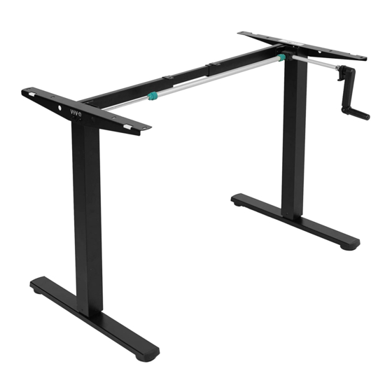
Black compact crank height adjustable desk frame
Hide thumbs
Also See for DESK-M051MB:
- Manual (9 pages) ,
- Instruction manual (12 pages) ,
- Assembly manual (16 pages)
Advertisement
Quick Links
Black Compact Crank Height Adjustable Desk Frame
Instruction Manual
SKU: DESK-M051MB
Scan the QR code with your mobile device or follow the link
for helpful videos and specifications related to this product.
https://vivo-us.com/products/desk-m051mb
GET IN TOUCH | Monday-Friday from 7:00am-7:00pm CST
help@vivo-us.com
www.vivo-us.com
Chat live with an agent!
309-278-5303
Advertisement

Subscribe to Our Youtube Channel
Related Manuals for Vivo DESK-M051MB


Summary of Contents for Vivo DESK-M051MB
- Page 1 Black Compact Crank Height Adjustable Desk Frame Instruction Manual SKU: DESK-M051MB Scan the QR code with your mobile device or follow the link for helpful videos and specifications related to this product. https://vivo-us.com/products/desk-m051mb GET IN TOUCH | Monday-Friday from 7:00am-7:00pm CST help@vivo-us.com...
-
Page 2: Package Contents
WARNING! If you do not understand these directions, or if you have any doubts about the safety of the installation, please call a qualified technician. Check carefully to make sure there are no missing or defective parts. Improper installation may cause damage or serious injury. Do not use this product for any purpose that is not explicitly specified in this manual and do not exceed weight capacity. -
Page 3: Assembly Steps
ASSEMBLY STEPS STEP 1 Loosen the two set screws on the telescopic crossbar (A) using the Allen wrench (S-E). Adjust the crossbar length to suit the desktop. Retighten all screws. STEP 2 Place the crossbar spacer (D) on the leg (B) as shown. Attach the telescopic crossbar to the legs (B, C) as shown using M6x12mm bolts (S-A), and tighten with the Allen wrench (S-E). - Page 4 STEP 4 Loosen the knob on the socket end of the sync rod (F) and slide the sync rod onto the shaft of the leg with gearbox. Tighten the knob. STEP 5 Loosen the knob on the other end of the sync rod and extend the hex shaft into the socket in the leg, making sure the shaft is fully inserted.
- Page 5 STEP 6 Place the frame upside down on desktop and drill pilot holes for the screws. Use a 3/32” or 3mm bit, and drill holes to a depth of 3/8” (10mm). Readjust the sync rod if necessary. STEP 7 Insert the anti-vibration pads (S-D) into the desktop mounting holes in the crossbar and side brackets.
- Page 6 STEP 8 Loosen the set screw on the crank (E) using the Allen wrench (S-E). Extend the crank into the gearbox, and with the front of the support plate flush with the front of the desktop, retighten the set screw. Using the module support plate, mark drilling locations with a pencil. Drill 3/8” (10mm) deep pilot holes under the desktop with a 5/64”...
- Page 7 STEP 10 If necessary, adjust foot pads to level desk. To operate the desk, pull out and rotate the crank. When not in use, push the crank back in and fold the handle. CAUTION! Do not exceed desk weight limit. Keep area of vertical motion free of obstacles.
- Page 8 - 92% within < 3hr www.vivo-us.com : < 15 M AVG. RESOLUTION TIME (within office hrs) Chat live with an agent! : 5M 4S AVG. RESOLUTION TIME 309-278-5303 (within office hrs) FOR MORE VIVO PRODUCTS, CHECK OUT OUR WEBSITE AT: www.vivo-us.com...
Need help?
Do you have a question about the DESK-M051MB and is the answer not in the manual?
Questions and answers