Table of Contents
Advertisement
Advertisement
Chapters
Table of Contents
Troubleshooting

Subscribe to Our Youtube Channel
Related Manuals for opti-solar SP Series


Summary of Contents for opti-solar SP Series
- Page 1 Solar Hybrid Inverter SP Series & SP UPS User Manual...
- Page 2 This manual includes 2 sections. Section1 is for Solar Hybrid Inverter SP Series; and section 2 is for SP UPS. Please refer to the section depending on what model you bought.
-
Page 3: (Section 1)
(Section 1) Solar Hybrid Inverter SP Series Manual... -
Page 4: Table Of Contents
(Section 1)......................3 PREFACE..............5 1-1 Conventions Used....................5 1-2 Glossary......................5 INTRODUCTION ............5 2-1 Description ......................5 2-2 Features......................6 2-3 Important Notices ....................6 2-4 Appearance ......................6 2-4-1 Front Panel ...................6 2-4-2 Outline....................8 INSTALLATION ............12 3-1 Safety......................12 3-1-1 Positioning..................12 3-1-2 Transporting ..................12 3-1-3 Installation..................13 3-1-4 Operation....................13 3-1-5 Maintenance and Service ..............13... -
Page 5: Preface
INTRODUCTION 2-1 Description The Solar SP series is designed to have access to dual input source; one is AC source from a grid, and the other is DC source from a solar array. This series is a powerful all-in-one solution, not only delivering unsurpassed clean true sine wave output power and combining this with a selectable multistage battery charging current but also converting sunlight into clean energy. -
Page 6: Features
offers the best price-performance ratio in the industry. 2-2 Features 1. Multiple microprocessor design base 2. Compatible with both linear and non-linear load 3. Stronger charger to support batteries of up to 600AH 4. 24-hour inverter operation 5. DC start and automatic self-diagnostic function 6. - Page 7 2. Up-key: Use to select upward the Solar SP status on LCD. 3. Down-key: Use to select downward the Solar SP status on LCD. Beside, press it simultaneously with the Up-key to switch off the Solar SP. 4. Enter-Key: It is pressed with the Down-key to turn on the Solar SP. In battery operation mode, press it with Up-key at the same time to disable the buzzer.
-
Page 8: Outline
2-4-2 Outline Rack Mount Type [1.2KVA] [2.4KVA/ 3.6KVA]... - Page 9 Wall Mounted Type [1.2KVA]...
- Page 10 [2.4KVA /3.6KVA]...
- Page 11 [5KVA/ 6KVA/ 8KVA]...
-
Page 12: Installation
INSTALLATION 3-1 Safety 3-1-1 Positioning 1. Do not put the Solar SP on rugged or declined surface. 2. Do not install the Solar SP system near water or in damp environments. 3. Do not install the Solar SP system where it will be exposed to direct sunlight or heat. -
Page 13: Installation
3-1-3 Installation Connect the Solar SP system only to a grounded shockproof wiring system to avoid electric shocks resulting from current leakage. 2. Place cables in such a way that no one can step on or trip over them. 3. Keep wire lengths between the array and the Solar SP as short as possible to minimize copper losses. -
Page 14: Mounting
3-2 Mounting 1. Make sure a wall surface or a solid place can support the Solar SP. 2. Mark the bracket hole positions of the Solar SP on the wall. Hole Diameter SP1200~SP3600 SP5000~SP8000 Upper Hole 9.5mm 15mm Lowe Lower Hole 10mm 3. -
Page 15: Wiring
3-3 Wiring 3-3-1 Inspection 1. The system may be installed and wired only by qualified electricians in accordance with applicable safety regulations. 2. When installing the electrical wiring, please note the nominal amperage of your incoming feeder. 3. Inspect the packaging carton and its contents for damage. Please inform the transport agency immediately should you find signs of damage. - Page 16 3. DC Input Terminals - Array (Input): Make sure the open circuit voltage (Voc) of the PV array is less than the DC maximum charge voltage (See 6-1 Specification) and the short circuit current (Isc) is less than DC maximum charge current (50A). Recommend DC wire size: Capacity Size...
- Page 17 4. Built-in Fuses/ Breakers Between Battery and Solar SP: Model Fuse 1.2KVA 20A/32VDC * 6pcs 2.4KVA 20A/32VDC * 6pcs 3.6KVA 30A/32VDC * 6pcs 5.0KVA 20A/32VDC * 16pcs 6.0KVA 20A/32VDC * 10pcs 8.0KVA 20A/32VDC *16pcs Between Solar Array and Battery: Model Fuse 1.2KVA 30A/32VDC * 2pcs...
- Page 18 6. Battery: Connect the battery’s terminals to the terminals for the battery of the Solar SP and make sure of the correct connection of the electric polarity. Recommend AC wire size: Model Size 1.2KVA 22mm 2.4KVA 22mm 3.6KVA 38mm 5.0KVA 80mm 6.0KVA 60mm...
-
Page 19: Operation
OPERATION 4-1 Prior to Startup 1. Ensure the Solar SP is in a suitable position. 2. Check that input cord is secured. 3. Make sure the load is disconnected or in the “OFF” position. 4. Check if input voltage meets the Solar SP rating required. 5. - Page 20 4. LCD Display Menu Use Up/Down key to select menu-displays of the LCD described below. This screen will refresh once the system power is enabled. Status Rated Spec Voltage Frequency Battery Status...
- Page 21 Output Power Temperature History Record 5. Input Voltage Range Setting After INVERTER startup, press the Down-key to find the screen and then press Enter-key for setting. Input Voltage Adjust A. In this screen, press Enter-key to enter the following steps for input voltage and frequency adjustment.
- Page 22 D. Once the correct voltage is selected, press Enter-key again to save the selection. 6. Output Voltage / Frequency Setting Output Voltage & Frequency Adjust A. In this screen, press Enter-key to enter the following steps for output voltage and frequency adjustment. B.
- Page 23 7. AC/DC Prior Setting (Option) Functioning only under AC Mode. AC/DC Prior Adjust A. In this screen, press Enter-key to enter the following steps for AC/DC prior adjustment. B. The cursor ( ) will pop up to indicate the AC/DC prior. C.
- Page 24 to the time adjustment. The time period (15Sec., 30Sec., 45Sec., and 60Sec. is selectable) for next detecting can be adjusted by the same key operation. D. Press Enter-key again to save the selection. 9. Battery Shutdown Voltage & Current Setting (48V/ 24V) Battery Shutdown Voltage &...
- Page 25 10. Battery Charging Current Setting Battery Charging Current Adjust A. In this screen, press Enter-key twice to enter the following steps for battery charging current adjustment. B. The cursor ( ) will pop up to indicate the battery charging current. C.
-
Page 26: Operation Modes
4-4 Operation Modes 4-4-1 System Block Diagram DC INPUT AC INPUT 4-4-2 Normal Operation There are two main loops when AC utility is normal and DC electricity is generated from solar array under sufficient sunlight: the AC loop and the battery charging loop. - Page 27 4-4-4 AC Utility Failure at Night The AC output comes from battery, passing through DC/AC inverter and static switch within during the battery backup time. DC INPUT AC INPUT...
-
Page 28: New Lcd Settings
NEW LCD SETTINGS 1. I / P Voltage Range Setting Default : Input Voltage : 220V (110V) LO = 170V(85V), HI = 270V(135V). LO : 120V ~ 200V(60V ~ 100V) One Touch: +/- 1V HI : 250V ~ 280V(125V ~ 140V) One Touch: +/- 1V Mark : 1. - Page 29 6.Battery Shutdown Voltage & Current Setting (48V/ 24V) Default: MIDDLE HIGH: 42V (21V) / MIDDLE: 40V (20V) / LOW: 38V (19V) Selectable Mark : 1. Low Voltage warning point: 42.5V (21.5V) 2. Press Enter to enable the setting. No need to re-start the inverter. 7.Battery Charging Current Setting Default: Middle LOW (100AH) - MIDDLE (300AH) - HIGH (600AH)
-
Page 30: Appendix
APPENDIX 5-1 Specification SP1200-SW SP2400-SW SP3600-SW Model SP1200-SR SP2400-SR SP3600-SR Capacity VA / Watt 1.2KVA / 800W 2.4KVA / 1600W 3.6KVA / 2400W Nominal Voltage 230Vac; 120Vac Acceptable Voltage Range 120-270Vac ; 60-135Vac Frequency 50Hz / 60Hz ( 45Hz - 70Hz) AC Input Voltage Line Low Transfer... - Page 31 230Vac (220V or 240VAC re-settable via LCD panel); Voltage 120Vac (110V or 115VAC re-settable via LCD panel) Voltage Regulation (Batt. Mode) < 3% RMS for entire battery voltage range Frequency 50Hz or 60Hz Frequency Regulation (Batt. Mode) 50Hz or 60Hz± 0.1Hz Output Power Factor 0.67...
- Page 32 SP1200-SW SP2400-SW SP3600-SW Model SP1200-SR SP2400-SR SP3600-SR Capacity VA / Watt 1.2KVA / 800W 2.4KVA / 1600W 3.6KVA / 2400W Battery Voltage 24Vdc 24Vdc 24Vdc Battery Backup Time Depends on System Load and Battery Capacity Max. Charging Current (5 steps selectable) UPS status, I/P&O/P Voltage Frequency, Load%, Display Battery Voltage &...
- Page 33 Model SP5000-SW SP6000-SW SP8000-SW Capacity VA / Watt 5KVA / 4000W 6KVA / 6000W 8KVA / 8000W Nominal Voltage 230Vac; 120Vac 230Vac only Acceptable Voltage Range 120-270Vac ; 60-135Vac 120-270Vac 50Hz / 60Hz Frequency 50Hz / 60Hz ( 45Hz - 70Hz) ( 45Hz - 70Hz) AC Input Voltage...
- Page 34 223Vac (220V or 240VAC re-settable via LCD panel); Voltage 230Vac 120Vac (110V or 115VAC re-settable via LCD panel) Voltage Regulation (Batt. Mode) < 3% RMS for entire battery voltage range Frequency 50Hz or 60Hz Output Frequency Regulation (Batt. Mode) ± 0.1Hz Power Factor Waveform Pure Sinewave...
- Page 35 SP5000-SW SP6000-SW SP8000-SW Capacity 5KVA / 4000W 5KVA / 4000W 6KVA / 6000W 8KVA / 8000W Battery Voltage 24Vdc 48Vdc Battery Backup Time Depends on System Load and Battery Capacity Max. Charging Current (5 steps selectable) UPS status, I/P&O/P Voltage Frequency, Load%, Display Battery Voltage &...
-
Page 36: Trouble Shooting
5-2 Trouble Shooting No. Solar SP STATUS POSSIBLE CAUSE ACTION AC utility power is normal. The Solar SP is Charger PCB is damaged. Replace the charger PCB. running normally, but the fault LED lights up. Fan is damaged. Replace the fan. Buzzer beeps continuously. - Page 37 (Section 2) SP UPS Manual...
- Page 38 1. INTRODUCTION ..........……..2. SAFTY INSTRUCTION....……...………….…..3. CABLE CONNECTION......……..……..…..4. SYSTEM DESCRIPTION.....……..……..…... 5. UPS OPERATION .........……... 6. TROUBLE SHOOTING GUIDE.......….…..… 7. OPERATION MODES OF THE UPS ....……..8. SPECIFICATION OF SP UPS....….....
-
Page 39: Introduction
1. INTRODUCTION 1.1 General Description The SP UPS, a powerful all-in-one solution, delivers unsurpassed clean true sine wave output power and combines this with a selectable multistage battery charging current. Applicable for any kind of loads such as air conditioner, home appliances, consumer electronic and office equipments. This series features a durable &... -
Page 40: Safty Instruction
2. SAFTY INSTRUCTION 2.1 Transporting 1. Disconnect all power cables if necessary. 2. Be careful not to damage the UPS while transporting. 3. Don‘t move the UPS upside down. 4. Please transport the UPS system only in the original packaging (to protect against shock and impact). - Page 41 2.4 Operation 1. Do not disconnect the mains cable on the UPS system or the building wiring socket outlet during operations since this would cancel the protective ground of the UPS system and of all connected loads. 2. The UPS has its own internal power source (batteries). The output terminals may be live even when the UPS is not connected to the AC supply.
-
Page 42: Cable Connection
3. CABLE CONNECTION 3.1 Inspection 1. The system may be installed and wired only by qualified electricians in accordance with applicable safety regulations. 2. When installing the electrical wiring, please note the nominal amperage of your incoming feeder. 3. Inspect the packaging carton and its contents for damage. Please inform the transport agency immediately should you find signs of damage. -
Page 43: System Description
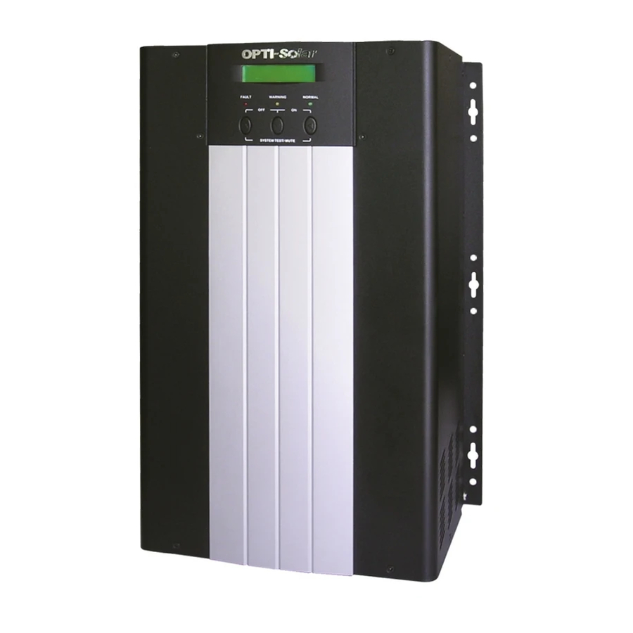
4. SYSTEM DESCRIPTION 4.1 Front Panel Description for LCD Model 1. LCD Display: This indicates the UPS operation information, including UPS status, input/output voltage, input/output frequency, battery voltage, battery capacity left, output load, inside temperature, and the times of history events. 2. - Page 44 6. Warning LED (yellow): To indicate the UPS is in the status of overload, bypass and battery back-up. 7. Normal LED (green): To indicate the UPS is operating normally. 8. ON/TEST/MUTE key: It should be pressed with the control key simultaneously to switch on UPS, do UPS auto-test in normal AC mode and turn off the buzzer in battery operation.
- Page 45 2.4KVA / 3.6KVA Rack Mount Type...
- Page 46 1.2KVA Wall Mounted Type...
- Page 47 2.4KVA / 3.6KVA Wall Mounted Type...
- Page 48 5KVA / 6KVA / 8KVA Wall Mounted Type...
-
Page 49: Ups Operation
5. UPS OPERATION 5.1 Check Prior to Start Up 1. Ensure the UPS is in a suitable positioning. 2. Check input cord is secured. 3. Make sure the load is disconnected or in the “OFF” position. 4. Check if input voltage meets the UPS rating required. 5.2 Storage Instruction Disconnect input power in rear panel if you will not use it for long period. - Page 50 4. LCD Display Menu Use Up/Down key to select menu-displays of the LCD described below. This screen will refresh once the system power is enabled. Rated Spec Status Voltage Frequency...
- Page 51 Battery Status Output Power Temperature History Record...
- Page 52 Input Voltage Range Setting After INVERTER startup, press the Down-key to find the screen and then press Enter-key for setting. Input Voltage Adjust A. In this screen, press Enter-key to enter the following steps for input voltage and frequency adjustment. B.
- Page 53 Output Voltage / Frequency Setting Output Voltage & Frequency Adjust A. In this screen, press Enter-key to enter the following steps for output voltage and frequency adjustment. B. The cursor ( ) will pop up to indicate the output voltage and frequency newly selected.
- Page 54 AC/DC Prior Setting (Option) Functioning only under AC Mode. AC/DC Prior Adjust A. In this screen, press Enter-key to enter the following steps for AC/DC prior adjustment. B. The cursor ( ) will pop up to indicate the AC/DC prior. C.
- Page 55 Green Power On/Off & Load & Time Setting (Option) Functioning only under INVERTER Mode. Green Power On/Off & Load & Time Adjust A. In this screen, press Enter-key twice to enter the following steps for Green Power On/Off adjustment. B. The cursor ( ) will pop up to indicate the Green Power On/Off.
- Page 56 Battery Shutdown Voltage & Current Setting (48V/ 24V) Battery Shutdown Voltage & Current Adjust A. In this screen, press Enter-key to enter the following steps for battery shutdown voltage adjustment. B. The cursor ( ) will pop up to indicate the battery shutdown voltage.
- Page 57 B. The cursor ( ) will pop up to indicate the battery charging current. C. Use Up or Down-key to adjust the battery charging current (LOW: 100AH, MIDDLE: 300AH, HIGH: 600AH is selectable). D. Once the correct battery charging current is selected, press Enter-key again to save the selection.
-
Page 58: Trouble Shooting Guide
6. TROUBLE SHOOTING GUIDE 6.1 For LCD Model The following guideline may be helpful for basic problem solving. UPS STATUS POSSIBLE CAUSE ACTION 1.Charger PCB is AC utility power is 1. Replace the normal. UPS is running damaged. charger PCB. normally, but fault 2.Fan is damaged. - Page 59 UPS STATUS POSSIBLE CAUSE ACTION AC utility power 1. AC utility power 1. Reduce the less fails .The load is failure. critical load in supplied by battery order to extend 2. AC input power. Buzzer alarm backup time. connection may sounds every 4 be not correct.
-
Page 60: Operation Modes Of The Ups
7. OPERATION MODES OF THE UPS 7.1 UPS System Block Diagram 7.2 Normal Operation There are two main loops when AC utility is normal: the AC loop and the battery charging loop. The AC output power comes from AC utility input and passes through static switch to support power to load. -
Page 61: Specification Of Sp Ups
8. SPECIFICATION OF SP UPS SP1200-UR SP2400-UR SP3600-UR Model SP1200-UW SP2400-UW SP3600-UW 1.2KVA / 2.4KVA / 3.6KVA / Capacity VA / Watt 800W 1600W 2400W Nominal Voltage 220Vac; 110Vac Acceptable Voltage 120-275Vac ; 90-135Vac Range Frequency 50Hz / 60Hz ( 45Hz - 70Hz) Input Line Low Transfer 120VAC ±... - Page 62 SP1200-UR SP2400-UR SP3600-UR Model SP1200-UW SP2400-UW SP3600-UW 1.2KVA / 2.4KVA / 3.6KVA / Capacity VA / Watt 800W 1600W 2400W Battery Voltage 24Vdc 24Vdc 24Vdc Backup Time (at full load) long time available Battery Max. Charging Current (5 steps selectable) UPS status, I/P&O/P Voltage Frequency, Load%, Battery Voltage &...
- Page 63 Model SP5000-UW SP6000-UW SP8000-UW 6KVA / Capacity VA / Watt 5KVA / 4000W 8KVA / 8000W 6000W Nominal Voltage 220Vac; 110Vac 220Vac only Acceptable Voltage 120-275Vac ; 90-135Vac 120-275Vac Range 50Hz / 60Hz Frequency 50Hz / 60Hz ( 45Hz - 70Hz) ( 45Hz - 70Hz) Input Line Low Transfer...
- Page 64 Model SP5000-UW SP6000-UW SP8000-UW 5KVA / 6KVA / 8KVA / Capacity VA / W 4000W 6000W 8000W Battery Voltage 24Vdc 48Vdc Backup Time (at full load) long time available Battery Max. Charging Current (5 steps selectable) UPS status, I/P&O/P Voltage Frequency, Load%, Battery Voltage &...
Need help?
Do you have a question about the SP Series and is the answer not in the manual?
Questions and answers