Table of Contents
Advertisement
Advertisement
Table of Contents

Related Manuals for opti-solar SP3000 Initial-P


Summary of Contents for opti-solar SP3000 Initial-P
- Page 1 User Manual Solar Hybrid Inverter SP Initial Series Version: 1.1...
-
Page 2: Table Of Contents
Table Of Contents ABOUT THIS MANUAL ............................. 1 Purpose ................................1 Scope ................................1 SAFETY INSTRUCTIONS ..........................1 INTRODUCTION ............................... 2 Features ................................2 Basic System Architecture ..........................2 Product Overview ............................. 3 INSTALLATION ..............................4 Unpacking and Inspection..........................4 Preparation .............................. -
Page 3: About This Manual
ABOUT THIS MANUAL Purpose This manual describes the assembly, installation, operation and troubleshooting of this unit. Please read this manual carefully before installations and operations. Keep this manual for future reference. Scope This manual provides safety and installation guidelines as well as information on tools and wiring. SAFETY INSTRUCTIONS WARNING: This chapter contains important safety and operating instructions. -
Page 4: Introduction
INTRODUCTION This is a multi-function SP Initial Series, combining functions of inverter, solar charger and battery charger to offer uninterruptible power support with portable size. Its comprehensive LCD display offers user-configurable and easy-accessible button operation such as battery charging current, AC/solar charger priority, and acceptable input voltage based on different applications. -
Page 5: Product Overview
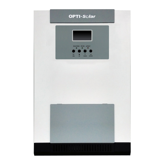
Product Overview side view SP5000 Initial-P/SP5000 Initial-M SP3000 Initial-P/SP3000 Initial 1. LCD display 2. Status indicator 3. Charging indicator 4. Fault indicator 5. Function buttons 6. Power on/off switch 7. AC input 8. AC output 9. PV input 10. Battery input 11. -
Page 6: Installation
INSTALLATION Unpacking and Inspection Before installation, please inspect the unit. Be sure that nothing inside the package is damaged. You should have received the following items inside of package: The unit x 1 User manual x 1 Communication cable x 1 ... -
Page 7: Battery Connection
To reduce risk of injury, please use the proper recommended cable as below. Recommended battery cable size: Model Wire Size Torque value(max) Cable (mm SP3000 Initial-P 1 x 4AWG SP3000 Initial-M 2 Nm SP5000 Initial-P 1 x 2AWG SP5000 Initial-M Please follow below steps to implement battery connection: 1. - Page 8 5. Insert the battery wires flatly into battery connectors of inverter and make sure the bolts are tightened with torque of 2 Nm in clockwise direction. Make sure polarity at both the battery and SP Initial Series is correctly connected and conductors are tightly screwed into the battery terminals. Recommended tool: #2 Pozi Screwdriver 6.
-
Page 9: Ac Input/Output Connection
AC input. The recommended spec of AC breaker is 32A for SP3000 Initial-P/SP3000 Initial-M and 50A for SP5000 Initial-P/SP5000 Initial-M. CAUTION!! There are two terminal blocks with “IN” and “OUT” markings. Please do NOT mis-connect input and output connectors. -
Page 10: Pv Connection
Take SP3000 Initial-P as an example to select proper PV module. After considering Voc of PV module not exceed 60Vdc and max. Vmpp of PV module close to 30Vdc or within 30Vdc ~ 32Vdc, we can choose PV module with below specification. - Page 11 Take SP5000 Initial-P as an example to select proper PV module. After considering Voc of PV module not exceed 105Vdc and max. Vmpp of PV module close to 60Vdc or within 56Vdc ~ 72Vdc, we can choose PV module with below specification.
-
Page 12: Final Assembly
5. To ensure wires are securely connected, you fix wires to the strain relief with cable tie. Final Assembly After connecting all wirings, please put bottom cover back by screwing two screws as shown below. Communication Connection Please use supplied communication cable to connect to inverter and PC. Insert bundled CD into a computer and follow on-screen instruction to install the monitoring software. -
Page 13: Operation
OPERATION Power ON/OFF Side view of unit Once the unit has been properly installed and the batteries are connected well, simply press On/Off switch (located on the button of the case) to turn on the unit. Operation and Display Panel The operation and display panel, shown in below chart, is on the front panel of the inverter. -
Page 14: Lcd Display Icons
LCD Display Icons Icon Function description Input Source Information Indicates the AC input. Indicates the PV input Indicate input voltage, input frequency, PV voltage, charger current (if PV in charging for 3K models), charger power (only for MPPT models), battery voltage. - Page 15 In battery mode, it will present battery capacity. Load Percentage Battery Voltage LCD Display < 1.85V/cell 1.85V/cell ~ 1.933V/cell Load >50% 1.933V/cell ~ 2.017V/cell > 2.017V/cell < 1.892V/cell 1.892V/cell ~ 1.975V/cell Load < 50% 1.975V/cell ~ 2.058V/cell > 2.058V/cell Load Information Indicates overload.
-
Page 16: Lcd Setting
Utility provides power to the loads only when battery voltage drops to either low-level warning voltage or the setting point in program 12. Available options in SP3000 Initial-P/SP3000 Initial-M model: Maximum charging current: To configure total charging current for solar and utility chargers. - Page 17 70A (only for PWM model) Available options in SP5000 Initial-P/SP5000 Initial-M: Maximum charging current: To configure total charging current for solar and utility 50A (default for PWM model) 60A (default for MPPT model) chargers. (Max. charging current = utility charging current + solar charging current) 100A 110A...
- Page 18 Available options in SP3000 Initial-P/SP3000 Initial-M: 25A (default) Available options in SP5000 Initial-P/SP5000 Initial-M: Maximum utility charging current Note: If setting value in program 02 is smaller than 30A (default) that in program in 11, the inverter will apply charging current from program 02 for utility charger.
- Page 19 Available options in SP3000 Initial-P/SP3000 Initial-M: Battery fully charged 24.5V 25.5V 26.5V 27V (default) 27.5V Setting voltage point back to battery mode when selecting “SBU priority” or 28.5V “Solar first” in program 01. Available options in SP5000 Initial-P/SP5000 Initial-M: Battery fully charged...
- Page 20 If SP Initial Series is working in Line, Standby or Fault mode, charger source can be programmed as below: Solar first Solar energy will charge battery as first priority. Utility will charge battery only when solar energy is not available. Utility first Utility will charge battery as first priority.
- Page 21 Record enable Record disable (default) Record Fault code SP3000 Initial-P/SP3000 Initial-M default setting: 28.2V SP5000 Initial-P/SP5000 Initial-M default setting: 56.4V Bulk charging voltage (C.V voltage) If self-defined is selected in program 5, this program can be set up. Setting range is from 25.0V to 31.5V for 3KVA/3KVA Plus model and 48.0V to 61.0V for 5KVA model.
-
Page 22: Display Setting
Display Setting The LCD display information will be switched in turns by pressing “UP” or “DOWN” key. The selectable information is switched as below order: input voltage, input frequency, PV voltage, charging current, charging power (SP 3000/5000Initial-M), battery voltage, output voltage, output frequency, load percentage, load in Watt, load in VA, load in Watt, DC discharging current, main CPU Version and second CPU Version. - Page 23 Output frequency=50Hz Output frequency Load percent=70% Load percentage When connected load is lower than 1kVA, load in VA will present xxxVA like below chart. Load in VA When load is larger than 1kVA (≧1KVA), load in VA will present x.xkVA like below chart. When load is lower than 1kW, load in W will present xxxW like below chart.
- Page 24 Battery voltage=25.5V, discharging current=1A Battery voltage/DC discharging current Main CPU version 00014.04 Main CPU version checking Secondary CPU version 00003.03 Secondary CPU version checking...
-
Page 25: Operating Mode Description
Operating Mode Description Operation mode Description LCD display Charging by utility and PV energy. Standby mode / Power saving mode Charging by utility. Note: *Standby mode: The inverter is No output is supplied by the not turned on yet but at this unit but it still can charge time, the inverter can charge batteries. - Page 26 Operation mode Description LCD display Charging by utility and PV energy. The unit will provide output power from the mains. It will Line Mode also charge the battery at Charging by utility. line mode. Power from battery and PV energy. The unit will provide output Battery Mode power from battery and PV...
-
Page 27: Fault Reference Code
Fault Reference Code Fault Code Fault Event Icon on Fan is locked when inverter is off. Over temperature Battery voltage is too high Battery voltage is too low Output short circuited or over temperature is detected by internal converter components. Output voltage is abnormal. -
Page 28: Specifications
SPECIFICATIONS Table 1 Line Mode Specifications INVERTER MODEL SP3000 Initial-P SP5000 Initial-P SP3000 Initial-M SP5000 Initial-M Input Voltage Waveform Sinusoidal (utility or generator) Nominal Input Voltage 230Vac 170Vac± 7V (UPS); Low Loss Voltage 90Vac± 7V (Appliances) 180Vac± 7V (UPS); Low Loss Return Voltage 100Vac±... -
Page 29: Table 2 Inverter Mode Specifications
Table 2 Inverter Mode Specifications INVERTER MODEL SP3000 Initial-P SP5000 Initial-P SP3000 Initial-M SP5000 Initial-M Rated Output Power 3KVA/2.4KW 5KVA/4KW 3KVA/2.4KW 5KVA/4KW Pure Sine Wave Output Voltage Waveform 230Vac± 5% Output Voltage Regulation 50Hz Output Frequency Peak Efficiency Overload Protection 5s@≥150% load;... -
Page 30: Table 3 Charge Mode Specifications
Table 3 Charge Mode Specifications Utility Charging Mode INVERTER MODEL SP3000 Initial-P SP5000 Initial-P SP3000 Initial-M SP5000 Initial-M Charging Algorithm 3-Step 25Amp 60Amp 25Amp 60Amp AC Charging Current (Max) =230Vac) =230Vac) =230Vac) =230Vac) Bulk Charging 29.2 58.4 29.2 58.4 Flooded Battery Voltage 28.2... -
Page 31: Table 4 General Specifications
Table 4 General Specifications INVERTER MODEL SP3000 Initial-P SP5000 Initial-P SP3000 Initial-M SP5000 Initial-M Operating Temperature Range -10°C to 50°C Storage temperature -15°C~ 60°C Humidity 5% to 95% Relative Humidity (Non-condensing) Dimension (D*W*H), mm 100 x 285 x 334 100 x 300 x 440 100 x 285 x 334 100 x 300 x 440... -
Page 32: Trouble Shooting
TROUBLE SHOOTING Problem LCD/LED/Buzzer Explanation / Possible cause What to do Unit shuts down LCD/LEDs and buzzer automatically will be active for 3 The battery voltage is too low 1. Re-charge battery. during startup seconds and then (<1.91V/Cell) 2. Replace battery. process. -
Page 33: Appendix: Approximate Back-Up Time Table
Appendix: Approximate Back-up Time Table Model Load (VA) Backup Time @ 24Vdc 100Ah (min) Backup Time @ 24Vdc 200Ah (min) 1100 1200 1500 SP3000 Initial-P 1800 SP3000 Initial-M 2100 2400 2700 3000 Model Load (VA) Backup Time @ 48Vdc 100Ah (min)
Need help?
Do you have a question about the SP3000 Initial-P and is the answer not in the manual?
Questions and answers