Table of Contents
Advertisement
Advertisement
Table of Contents

Related Manuals for opti-solar SP Brilliant Series


Summary of Contents for opti-solar SP Brilliant Series
- Page 1 User Manual Solar Hybrid Inverter SP Brilliant Series...
-
Page 2: Table Of Contents
Table Of Contents ABOUT THIS MANUAL ............................. 1 Purpose ................................1 Scope ................................1 SAFETY INSTRUCTIONS ..........................1 INTRODUCTION ............................... 2 Features ................................2 Basic System Architecture ..........................2 Product Overview ............................. 3 INSTALLATION ..............................4 Unpacking and Inspection ..........................4 Preparation............................... -
Page 3: About This Manual
ABOUT THIS MANUAL Purpose This manual describes the assembly, installation, operation and troubleshooting of this unit. Please read this manual carefully before installations and operations. Keep this manual for future reference. Scope This manual provides safety and installation guidelines as well as information on tools and wiring. SAFETY INSTRUCTIONS WARNING: This chapter contains important safety and operating instructions. -
Page 4: Introduction
INTRODUCTION This is a multi-function inverter/charger, combining functions of inverter, MPPT solar charger and battery charger to offer uninterruptible power support with portable size. Its comprehensive LCD display offers user-configurable and easy-accessible button operation such as battery charging current, AC/solar charger priority, and acceptable input voltage based on different applications. -
Page 5: Product Overview
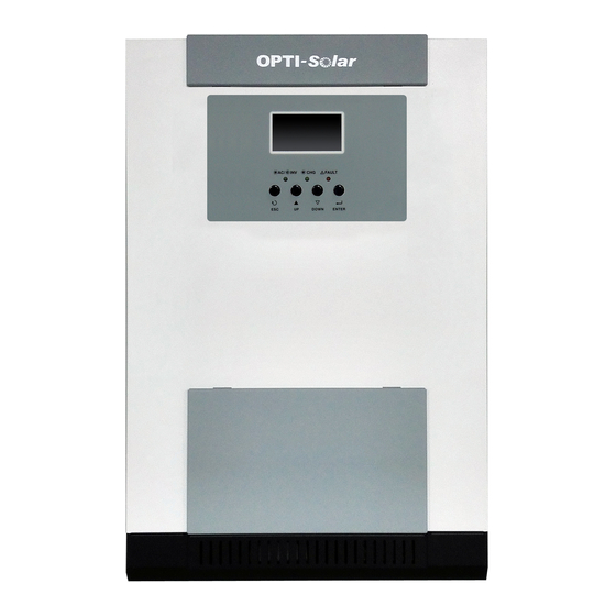
Product Overview 5KVA single model 5KVA parallel model 3KVA model 1. LCD display 2. Status indicator NOTE: For parallel model installation and operation, 3. Charging indicator please check separate parallel installation guide for 4. Fault indicator the details. 5. Function buttons 6. -
Page 6: Installation
INSTALLATION Unpacking and Inspection Before installation, please inspect the unit. Be sure that nothing inside the package is damaged. You should have received the following items inside of package: The unit x 1 User manual x 1 Communication cable x 1 ... -
Page 7: Battery Connection
Install the unit by screwing three screws. 3KVA/5KVA Model Battery Connection CAUTION: For safety operation and regulation compliance, it’s requested to install a separate DC over-current protector or disconnect device between battery and inverter. It may not be requested to have a disconnect device in some applications, however, it’s still requested to have over-current protection installed. - Page 8 3. Insert the ring terminal of battery cable flatly into battery connector of inverter and make sure the bolts are tightened with torque of 2-3 Nm. Make sure polarity at both the battery and the inverter/charge is correctly connected and ring terminals are tightly screwed to the battery terminals. WARNING: Shock Hazard Installation must be performed with care due to high battery voltage in series.
-
Page 9: Ac Input/Output Connection
AC Input/Output Connection CAUTION!! Before connecting to AC input power source, please install a separate AC breaker between inverter and AC input power source. This will ensure the inverter can be securely disconnected during maintenance and fully protected from over current of AC input. The recommended spec of AC breaker is 32A for 3KVA and 50A for 5KVA. -
Page 10: Pv Connection
5. Make sure the wires are securely connected. CAUTION: Important Be sure to connect AC wires with correct polarity. If L and N wires are connected reversely, it may cause utility short-circuited when these inverters are worked in parallel operation. CAUTION: Appliances such as air conditioner are required at least 2~3 minutes to restart because it’s required to have enough time to balance refrigerant gas inside of circuits. -
Page 11: Final Assembly
PV Module Selection: When selecting proper PV modules, please be sure to consider below parameters: 1. Open circuit Voltage (Voc) of PV modules not exceeds max. PV array open circuit voltage of inverter. 2. Open circuit Voltage (Voc) of PV modules should be higher than min. battery voltage. Solar Charging Mode INVERTER MODEL 3KVA / 5KVA... -
Page 12: Dry Contact Signal
check user manual of software inside of CD. Dry Contact Signal There is one dry contact (3A/250VAC) available on the rear panel. It could be used to deliver signal to external device when battery voltage reaches warning level. Unit Status Condition Dry contact port: NC &... -
Page 13: Operation
OPERATION Power ON/OFF Once the unit has been properly installed and the batteries are connected well, simply press On/Off switch (located on the button of the case) to turn on the unit. Operation and Display Panel The operation and display panel, shown in below chart, is on the front panel of the inverter. It includes three indicators, four function keys and a LCD display, indicating the operating status and input/output power information. -
Page 14: Lcd Display Icons
LCD Display Icons Icon Function description Input Source Information Indicates the AC input. Indicates the PV input Indicate input voltage, input frequency, PV voltage, battery voltage and charger current. Configuration Program and Fault Information Indicates the setting programs. Indicates the warning and fault codes. Warning: flashing with warning code. - Page 15 In battery mode, it will present battery capacity. Load Percentage Battery Voltage LCD Display < 1.717V/cell 1.717V/cell ~ 1.8V/cell Load >50% 1.8 ~ 1.883V/cell > 1.883 V/cell < 1.817V/cell 1.817V/cell ~ 1.9V/cell 50%> Load > 20% 1.9 ~ 1.983V/cell > 1.983 <...
-
Page 16: Lcd Setting
LCD Setting After pressing and holding ENTER button for 3 seconds, the unit will enter setting mode. Press “UP” or “DOWN” button to select setting programs. And then, press “ENTER” button to confirm the selection or ESC button to exit. Setting Programs: Program Description... - Page 17 60A (default) Appliances (default) If selected, acceptable AC input voltage range will be within 90-280VAC. AC input voltage range If selected, acceptable AC input voltage range will be within 170-280VAC. Saving mode disable If disabled, no matter connected load (default) is low or high, the on/off status of inverter output will not be effected.
- Page 18 3KVA model: 15A(default): 5KVA model: Maximum utility charging current 30A (default) Available options: 46V (default) Setting voltage point back to utility source when selecting “SBU priority” or “Solar first” in program 01. Available options: Battery fully charged Setting voltage point back to battery mode when selecting “SBU priority”...
- Page 19 If this inverter/charger is working in Line, Standby or Fault mode, charger source can be programmed as below: Solar first Solar energy will charge battery as first priority. Utility will charge battery only when solar energy is not available. Utility first Utility will charge battery as first priority.
-
Page 20: Display Setting
Bypass disable Bypass enable Overload bypass: (default) When enabled, the unit will transfer to line mode if overload occurs in battery mode. Record enable Record disable (default) Record Fault code Default setting: 56.4V Bulk charging voltage (C.V voltage) If self-defined is selected in program 5, this program can be set up. - Page 21 Selectable information LCD display Input Voltage=230V, output voltage=230V Input voltage/Output voltage (Default Display Screen) Input frequency=50Hz Input frequency PV voltage=60V PV voltage Current ≧10A MPPT Charging current Current < 10A MPPT Charging power MPPT charging power=500W Battery voltage=25.5V, discharging current=1A Battery voltage/ DC discharging current...
- Page 22 Output frequency=50Hz Output frequency Load percent=70% Load percentage When connected load is lower than 1kVA, load in VA will present xxxVA like below chart. Load in VA When load is larger than 1kVA (≧1KVA), load in VA will present x.xkVA like below chart. When load is lower than 1kW, load in W will present xxxW like below chart.
- Page 23 Main CPU version 00014.04 Main CPU version checking Secondary CPU version 00003.03 Secondary CPU version checking...
-
Page 24: Operating Mode Description
Operating Mode Description Operation mode Description LCD display Charging by utility. Standby mode / Power saving mode Note: *Standby mode: The inverter is Charging by PV energy. No output is supplied by the not turned on yet but at this unit but it still can charge time, the inverter can charge batteries. -
Page 25: Fault Reference Code
Power from battery and PV energy. The unit will provide output Battery Mode power from battery and PV power. Power from battery only. Fault Reference Code Fault Code Fault Event Icon on Fan is locked when inverter is off. Over temperature Battery voltage is too high Battery voltage is too low Output short circuited or over temperature is detected... -
Page 26: Warning Indicator
Warning Indicator Warning Warning Event Audible Alarm Icon flashing Code Fan is locked when Beep three times every inverter is on. second Battery is over-charged Beep once every second Low battery Beep once every second Overload Beep once every 0.5 second Output power derating Beep twice every 3 seconds Solar charger stops due... -
Page 27: Specifications
SPECIFICATIONS Table 1 Line Mode Specifications INVERTER MODEL 3KVA 5KVA Input Voltage Waveform Sinusoidal (utility or generator) Nominal Input Voltage 120Vac or 230Vac 95Vac±7V or 170Vac±7V (UPS) Low Loss Voltage 65Vac±7V or 90Vac±7V (Appliances) 100Vac±7V or 180Vac±7V (UPS); Low Loss Return Voltage 70Vac±7V or 100Vac±7V (Appliances) High Loss Voltage 140Vac±7V or 280Vac±7V... -
Page 28: Table 2 Inverter Mode Specifications
Table 2 Inverter Mode Specifications INVERTER MODEL 3KVA 5KVA Rated Output Power 3KVA/2.4KW 5KVA/4KW Pure Sine Wave Output Voltage Waveform ±5% 230Vac±5% Output Voltage Regulation 110/120VAC Output Frequency 60Hz or 50Hz Peak Efficiency Overload Protection 5s@≥150% load; 10s@110%~150% load Surge Capacity 2* rated power for 5 seconds Nominal DC Input Voltage 48Vdc... -
Page 29: Table 4 General Specifications
Table 3 Charge Mode Specifications Utility Charging Mode INVERTER MODEL 3KVA 5KVA Charging Current (UPS) 10/15A 20/30A =230Vac Flooded Bulk 58.4 Battery Charging AGM / Gel Voltage 56.4 Battery Floating Charging Voltage 54Vdc Charging Algorithm 3-Step Battery Voltage, per cell Charging Current, % 2.43Vdc (2.35Vdc) Voltage... -
Page 30: Trouble Shooting
TROUBLE SHOOTING Problem LCD/LED/Buzzer Explanation / Possible cause What to do Unit shuts down LCD/LEDs and buzzer automatically will be active for 3 The battery voltage is too low 1. Re-charge battery. during startup seconds and then (<1.91V/Cell) 2. Replace battery. process. -
Page 31: Appendix: Approximate Back-Up Time Table
Appendix: Approximate Back-up Time Table Model Load (VA) Backup Time @ 48Vdc 100Ah (min) Backup Time @ 48Vdc 200Ah (min) 1054 2107 1054 1200 1500 3KVA 1800 2100 2400 2700 3000 1288 1000 1500 2000 2500 5KVA 3000 3500 4000 4500 5000 Note: Backup time depends on the quality of the battery, age of battery and type of battery.
Need help?
Do you have a question about the SP Brilliant Series and is the answer not in the manual?
Questions and answers
Want to know what this code stand for UI40.00