Table of Contents
Advertisement
Quick Links
Advertisement
Table of Contents

Subscribe to Our Youtube Channel
Related Manuals for Acromag XCOM-6400


Summary of Contents for Acromag XCOM-6400
- Page 1 Artisan Technology Group is your source for quality new and certified-used/pre-owned equipment SERVICE CENTER REPAIRS WE BUY USED EQUIPMENT • FAST SHIPPING AND DELIVERY Experienced engineers and technicians on staff Sell your excess, underutilized, and idle used equipment at our full-service, in-house repair center We also offer credit for buy-backs and trade-ins •...
- Page 2 COM Express CPU Module USER’S MANUAL ACROMAG INCORPORATED 30765 South Wixom Road Wixom, MI 48393-2417 U.S.A. Tel: (248) 295-1541 Fax: (248) 624-9234 Copyright 2015, Acromag, Inc., Printed in the USA. Data and specifications are subject to change without notice. 8501003L...
-
Page 3: Table Of Contents
2.4 Default Hardware Configuration ................. 12 3.0 HARDWARE INFORMATION AND CONFIGURATION ........13 3.1 Module Hardware Configuration ................13 Fig. 3.1.a: XCOM-6400 Without Heat Spreader Top View ............13 Fig. 3.1.b: XCOM-6400 Bottom View ................... 14 Table 3.1.a: Configuration Switches ................... 15 3.2 Power Supply and Management ................. - Page 4 3.10 Ethernet ........................29 3.10.1 Configuring Wake On LAN ......................29 3.10.2 Configuring PXE Boot ........................29 3.11 Real Time Clock (RTC) ....................29 3.12 Security ........................30 Acromag, Inc. Tel: 248-295-1541 - 2 - - 2 - www.acromag.com http://www.acromag.com...
- Page 5 Fig. 3.14.5.c: Module Mounting Screw Locations ..............36 Fig. 3.14.5.d: SODIMM Assembly....................37 Fig. 3.14.5.e: XCOM-6400 with Heat Spreader and Active Heat Sink ........38 Fig. 3.14.5.f: XCOM-6400, ACEX-4620 Carrier Board, and Heat Spreader Assembly....39 3.15 Watchdog ......................... 39 4.0 BIOS INFORMATION AND CONFIGURATION .............
- Page 6 6.4 Reliability Prediction ....................46 Table 6.4.a: MTBF ........................46 6.5 Certificate of Volatility ....................47 APPENDIX A: COM-EXPRESS CONNECTOR (J4) PINOUT TABLE ......47 REVISION HISTORY ......................50 Acromag, Inc. Tel: 248-295-1541 - 4 - - 4 - www.acromag.com http://www.acromag.com...
-
Page 7: General Information
1.1 Intended Audience This users’ manual was written for technically qualified personnel who will be working with I/O devices using the XCOM-6400 CPU. It is not intended for a general, non-technical audience that is unfamiliar with computer-on-module (COM) devices and their application. -
Page 8: Product Summary
I/O it must be installed in a Type 6 R2.0 or R2.1 Com Express carrier board. WARNING: The XCOM-6400 must be installed onto a Type 6 carrier board conforming to R2.0 or R2.1 of the Com-Express Specification. Damage to the module and/or carrier may result if used with another carrier. -
Page 9: Related Material
XCOM-6400 module. COM-Express Module Base Specification Rev. 2.1 http://www.picmg.org The Acromag APTIO Haswell Core BIOS Manual For Acromag Products – Referred to hereafter as The APTIO Haswell Core BIOS Manual For Acromag Products. -
Page 10: Key Features And Benefits
USER’S MANUAL XCOM-6400 1.6 Key Features and Benefits The XCOM-6400 block diagram shown in Fig. 1.6.1 illustrates the key components and features that are summarized on the following pages. Fig. 1.6.a: XCOM-6400 Block Diagram 1.6.1 Intel® 4th Gen (Haswell) Core CPU Available as either a 2.4GHz quad-core i7 or a 1.6GHZ dual-core i5. -
Page 11: Intel Qm87 Chipset (Lynx Point) Pch
Super-I/O or TPM devices. SPI – The Serial Peripheral Interface is used for the onboard boot flash. This interface is available on the carrier for connection of Acromag, Inc. Tel: 248-295-1541 - 9 - - 9 - www.acromag.com... -
Page 12: Intel I217 Phy
Platform Modules (TPM). The TPM includes a cryptographic accelerator capable of computing a 2048-bit RSA signature in 200ms and a 1024-bit RSA signature in 40ms. Performance of the SHA-1 accelerator is 20μs per 64-byte block. Acromag, Inc. Tel: 248-295-1541 - 10 - - 10 - www.acromag.com... -
Page 13: Preparation For Use
It is important that the user employ satisfactory overall system design. It is understood and agreed by the Buyer and Acromag that this is the Buyer's responsibility. WARNING: This board utilizes static sensitive components and should only be handled at a static-safe workstation. -
Page 14: Carrier Board Considerations
Refer to the specifications section for loading and power requirements. Be sure that the system power supplies are able to accommodate the power requirements of the system boards, plus the installed Acromag board, within the voltage tolerances specified. In an air cooled assembly, the optional active heatsink must be used and adequate air circulation must be provided to prevent a temperature rise above the maximum operating. -
Page 15: Hardware Information And Configuration
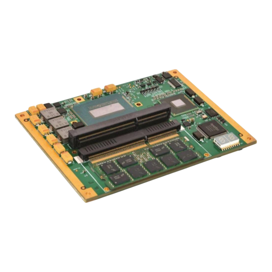
USER’S MANUAL XCOM-6400 3.0 HARDWARE INFORMATION AND CONFIGURATION 3.1 Module Hardware Configuration Fig. 3.1.a: XCOM-6400 Without Heat Spreader Top View Acromag, Inc. Tel: 248-295-1541 - 13 - - 13 - www.acromag.com http://www.acromag.com... - Page 16 USER’S MANUAL XCOM-6400 Fig. 3.1.b: XCOM-6400 Bottom View Acromag, Inc. Tel: 248-295-1541 - 14 - - 14 - www.acromag.com http://www.acromag.com...
-
Page 17: Power Supply And Management
3.2 Power Supply and Management 3.2.1 Power Options When using the Acromag ACEX-46XX carrier board, the carrier provides a 12V plus 5V standby power supply to the system module. When using a carrier board other than the ACEX-46XX, the module can be powered from either the 12V only, or 12V plus 5V standby power source. -
Page 18: Programmable Cpu Power Limits
USER’S MANUAL XCOM-6400 WARNING: The XCOM-6400 must be installed onto a Type 6 carrier board conforming to R2.0 or R2.1 of the Com-Express Specification. Damage to the module and/or carrier may result if used with another carrier. 3.2.2 Programmable CPU Power Limits... -
Page 19: Power Management
PL1. More details about programming these power limits using the BIOS setup utility are provided in The APTIO Haswell Core BIOS Manual For Acromag Products. 3.2.3 Power Management The XCOM-6400 module uses the Advanced Configuration and Power Interface (ACPI) 3.0 standard to provide user-managed power via the... -
Page 20: Cpu
S3, S4, or S5 support. 3.2.3.2 ACPI Wake-Up Events The XCOM-6400 module supports the following wake‐up events from the S3, S4, and S5 power states if 12V operating power or 5V standby power are provided by the power supply: ... -
Page 21: Active Processor Core Selection
More details about this feature are provided in The APTIO Haswell Core BIOS Manual For Acromag Products. 3.4 Platform Controller Hub (PCH) The Intel 8 Series QM87 Lynx Point PCH provides extensive I/O support, all of which is available on the COM-EXPRESS connector and is listed below: ... -
Page 22: System Memory
3.5 System Memory XCOM-6400 COM Express modules have two 204‐pin, right‐angle SO‐DIMM sockets (J1, J2) to accept DDR3L ECC SDRAM modules. At least one SDRAM module is required to make the system operational. - Page 23 Max of 2 HDMIs Max of 2 DVIs Max of 1 HDMI and 1 DVI Any 3 DisplayPort One VGA One eDP Acromag, Inc. Tel: 248-295-1541 - 21 - - 21 - www.acromag.com http://www.acromag.com...
-
Page 24: Pci Express Graphics (Peg)
3.1.a, “Configuration Switches”, for further information regarding these switches and their configuration. 3.6.3 VGA The XCOM-6400 COM Express module uses the Intel® Lynx Point controller to support the analog VGA interface The VGA interface features include: Integrated 180 Mhz 24‐bit RAMDAC ... - Page 25 (control/status) data information through the DVI cable. The BIOS will automatically detect installed devices that are using DVI interfaces, and will automatically configure the installed devices. Acromag, Inc. Tel: 248-295-1541 - 23 - - 23 - www.acromag.com...
- Page 26 HDMI and DisplayPort monitors. The processor supports silent streams over the HDMI and DisplayPort interfaces at 44.1 kHz, 48 kHz, 88.2 kHz, 96 kHz, 176.4 kHz, and 192 kHz sampling rates. Acromag, Inc. Tel: 248-295-1541 - 24 - - 24 - www.acromag.com...
-
Page 27: Embedded Displayport
The module can also generate a separate PC speaker signal, although most CODECs intercept this signal and pipe it out through the speakers attached to the CODEC. Enabling and configuring the HDA is discussed in The APTIO Haswell Core BIOS Manual For Acromag Products. 3.8 Storage I/O 3.8.1 SATA SATA (Serial Advance Technology Attachment) is the interface that connects the PCH to the supported mass storage devices (see below). -
Page 28: General I/O
To configure SATA operation, refer to The APTIO Haswell Core BIOS Manual For Acromag Products. Note: Although there are 6 SATA ports shown in the BIOS setup, there are only 4 ports available on the XCOM-6400. Ports 2 and 3 are unavailable. 3.9 General I/O 3.9.1 General Purpose I/O (GPIO) -
Page 29: Low Pin Count (Lpc)
Lane 6 is set as a one x1 interface, and must remain as such. Contact our Application Engineer if you need a custom PCI Express lane configuration. Acromag, Inc. Tel: 248-295-1541 - 27 - - 27 - www.acromag.com http://www.acromag.com... -
Page 30: Serial Ports
For further information regarding BIOS serial port configuration, refer to The APTIO Haswell Core BIOS Manual For Acromag Products. 3.9.6 SPI Flash The Intel® Lynx Point PCH chipset supports SPI‐compatible flash devices of up to 16MB flash ROM with two SPI chip‐select signals, SPI_CS[0:1]#. -
Page 31: Ethernet
3.10.1 Configuring Wake On LAN For information regarding how to configure Wake On Lan, refer to Section 4.1, "XCOM-6400 Special BIOS Features" and also The APTIO Haswell Core BIOS Manual For Acromag Products. 3.10.2 Configuring PXE Boot For information regarding how to boot from the network, refer to The APTIO Haswell Core BIOS Manual For Acromag Products. -
Page 32: Security
This behavior is normal. 3.12 Security 3.12.1 Trusted Platform Support The XCOM-6400 uses the Atmel AT97SC3204 fully integrated security module, which implements version 1.2 of the Trusted Computing Group (TCG) specification for Trusted Platform Modules (TPM). The TPM includes a cryptographic accelerator capable of computing a 2048-bit RSA signature in 200ms and a 1024-bit RSA signature in 40ms. -
Page 33: Enhanced Intel Speedstep Technology (Eist)
The Intel® HT Technology is enabled by default; no action by the operator is required. For further information on disabling support for this technology, refer to The APTIO Haswell Core BIOS Manual For Acromag Products. 3.13.2 Enhanced Intel SpeedStep Technology (EIST) ®... -
Page 34: Intel ® Active Management Technology
Refer to The APTIO Haswell Core BIOS Manual For Acromag Products and the appropriate processor Turbo Implementation Guide for more information. -
Page 35: Intel ® Matrix Storage Technology
For further information on configuring the TDP levels, refer to The APTIO Haswell Core BIOS Manual For Acromag Products. 3.14 Thermal Management ® The Intel Haswell processor contains a digital thermal sensor for each execution core and a thermal monitor to measure the processor’s... -
Page 36: Thermal Throttling
DIMM’s thermal sensor, refer to The APTIO Haswell Core BIOS Manual For Acromag Products. 3.14.5 Thermal Management Hardware Two types of thermal management hardware are available on the XCOM-6400 for managing and dissipating the thermal energy generated in the module: ... - Page 37 USER’S MANUAL XCOM-6400 Fig. 3.14.5.b: XCOM-6400 and Heat Spreader This is the XCOM-6400 module with the standard heat spreader installed. WARNING: Do not attempt to remove the heat spreader. There are no user- serviceable parts underneath. Once assembled to the XCOM-6400 module, the heat spreader should never need to be removed.
- Page 38 There are M6 threaded mounting holes on the spreader in the five locations per the COM Express specification. These same five holes are also clearance holes for M2.5 x 8mm screws that are to be used to mount the XCOM-6400 to any carrier, as shown in See Fig. 3.1.5.5.e below.
- Page 39 USER’S MANUAL XCOM-6400 The SODIMM assembly and its components are shown below. Fig. 3.14.5.d: SODIMM Assembly Acromag, Inc. Tel: 248-295-1541 - 37 - - 37 - www.acromag.com http://www.acromag.com...
- Page 40 USER’S MANUAL XCOM-6400 The XCOM-6400 module with the optional XHSA-6400 active (with fan) heat sink installed is shown below in Fig. 3.15.5.e. The XHSA-6400 would be used in air cooled applications. The XHSA-6400 is attached to the XCOM-6400's heat spreader with the 4 supplied M2.5 x 8 screws. No thermal grease has been provided with the XHSA-6400.
-
Page 41: Watchdog
USER’S MANUAL XCOM-6400 This is the XCOM-6400 module mounted onto the ACEX-4620 carrier board with the standard heat spreader installed. Fig. 3.14.5.f: XCOM-6400, ACEX-4620 Carrier Board, and Heat Spreader Assembly 3.15 Watchdog The XCOM-6400 features a software-triggered multi-stage watchdog solution. -
Page 42: Bios Information And Configuration
4.1 XCOM-6400 Special BIOS Features This section contains information on configuring features specific to the XCOM-6400. For other, more generic BIOS setup information, refer to The APTIO Haswell Core BIOS Manual For Acromag Products. Fig. 4.1.a: Acromag BIOS Setup Menu... - Page 43 RS-485 RTS output. This must be set to COM0 RS-485 RTS output when using RS-485 mode on COM0 of the ACEX-46XX carrier. Fig. 4.1.c: Acromag BIOS Setup Menu - GPO3 GPO3 can be selected be function either as GPO3 or as the COM1 RS- 485 RTS output.
-
Page 44: Drivers And Utilities
USER’S MANUAL XCOM-6400 ACPRESENT functionality is not available on the XCOM-6400. Select GPI3 to have normal GPI3 functionality. Fig. 4.1.e: Advanced BIOS Setup Menu - i217 LAN Port Configuration Link Speed and Wake On LAN can be configured in the NIC Configuration sub-menu: Fig. -
Page 45: Service And Repair
5.3 Where to Get Help If the problem persists, the next step should be to visit the Acromag worldwide web site at http://www.acromag.com. Our web site contains the most up-to-date product and software information. -
Page 46: Specifications
COM Express Module Base Specification Revision 2.1. 6.2 Power Requirements The power required to properly operate the XCOM-6400 module will vary depending on many variables, including the operating system, application software, and the components that the module is integrated with. See notes below for defined variables used to measure the following power values: +12VDC (5%) -
Page 47: Environmental Considerations
CPU throttling which will greatly affect system performance. WARNING: The supplied heat spreader is not intended to be a complete thermal solution. The XCOM-6400 must be used in conjunction with the optional XHSA-6400 (in an air-cooled environment only) or mounted inside a conduction enclosure/chassis with adequate heat removal capacity. -
Page 48: Reliability Prediction
Clear EEPROM memory by □ No ID and/or User Data erasing all bytes. Acromag Representative Name: Title: Email: Office Phone: Office Fax: Joseph Primeau Dir. of Sales solutions@acromag.com 248-295-0310 248-624-9234 Marketing Acromag, Inc. Tel: 248-295-1541 - 46 - - 46 - www.acromag.com http://www.acromag.com... -
Page 49: Certificate Of Volatility
USB7- DDI3_CTRLCLK_AUX+ DDI1_PAIR3+ USB6+ USB7+ DDI3_CTRLDATA_AUX- DDI1_PAIR3- USB_6_7_OC# USB_4_5_OC# DDI3_DDC_AUX_SEL NO CONNECT USB4- USB5- DDI3_PAIR0+ DDI2_PAIR0+ USB4+ USB5+ DDI3_PAIR0- DDI2_PAIR0- USB2- USB3- DDI3_PAIR1+ DDI2_PAIR1+ USB2+ USB3+ DDI3_PAIR1- D012_PAIR1- Acromag, Inc. Tel: 248-295-1541 - 47 - - 47 - www.acromag.com http://www.acromag.com... - Page 50 NO CONNECT NO CONNECT eDP_AUX- VCC_5V_SBY GPI3 VCC_5V_SBY PEG_RX10+ PEG_TX10+ NO CONNECT VCC_5V_SBY PEG_RX10- PEG_TX10- eDP_HPD VCC_5V_SBY PCIE_CLK_REF NO CONNECT PEG_RX11+ PEG_TX11+ PCIE_CLK_REF VGA_RED PEG_RX11- PEG_TX11- Acromag, Inc. Tel: 248-295-1541 - 48 - - 48 - www.acromag.com http://www.acromag.com...
- Page 51 For detailed signal descriptions, refer to the COM-Express Module Base Specification Rev. 2.1. The functionality of the signals on these pins as described in the COM Express Module Base Specification Rev. 2.1 is not available on the XCOM-6400 module. Acromag, Inc. Tel: 248-295-1541...
-
Page 52: Revision History
Haswell Core BIOS Manual For Acromag Products Removed leaded solder models. Customers advised to 25 SEP 2015 JGV/ARP contact factory. Added GPIO mapping from XCOM-6400 pin to PCH pin in 20 OCT 2015 Section 3.9.1. Corrected Shock and Vibration specifications. 04 MAY 2016 DAG/ARP Modify references to APTIO Core BIOS Manual;... - Page 53 Artisan Technology Group is your source for quality new and certified-used/pre-owned equipment SERVICE CENTER REPAIRS WE BUY USED EQUIPMENT • FAST SHIPPING AND DELIVERY Experienced engineers and technicians on staff Sell your excess, underutilized, and idle used equipment at our full-service, in-house repair center We also offer credit for buy-backs and trade-ins •...
Need help?
Do you have a question about the XCOM-6400 and is the answer not in the manual?
Questions and answers