
Related Manuals for Feig Electronic OBID ID CPR.03.20-CD


Summary of Contents for Feig Electronic OBID ID CPR.03.20-CD
- Page 1 MONTAGE ® OBID classic-pro INSTALLATION ID CPR.03.20-CD Multitag Reader Data-/Clock and RS232-TTL (deutsch / english) final public (B) 2008-09-23 M60100-2de-ID-B.doc...
- Page 2 ® OBID classic-pro Montage ID CPR.03.20-CD deutsche Version ab Seite 3 english version from page 14 FEIG ELECTRONIC GmbH Seite 2 von 24 M60100-2de-ID-B.doc...
- Page 3 Hinweise jederzeit dankbar. Die in diesem Dokument gemachten Installationsempfehlungen gehen von günstigsten Rahmenbedingun- gen aus. FEIG ELECTRONIC GmbH übernimmt weder Gewähr für die einwandfreie Funktion in system- fremden Umgebungen, noch für die Funktion des Gesamtsystems.
-
Page 4: Table Of Contents
Installation Montage..........................9 Anschluss ........................10 Konfiguration .......................11 4.3.1 Werks-Konfiguration......................11 4.3.2 Konfiguration neu laden ....................11 Normalbetrieb Digitale Eingänge ......................12 Data-/Clock Schnittstelle ....................13 RS232-TTL Schnittstelle .....................13 Lieferumfang Digital Inputs........................23 Data-/Clock Interface....................24 Asynchronous Interface: RS232-TTL ................24 FEIG ELECTRONIC GmbH Seite 4 von 24 M60100-2de-ID-B.doc... - Page 5 Obwohl dieses Gerät die zulässigen Grenzwerte für elektromagnetische Felder nicht ü- berschreitet, sollten Sie einen Mindestabstand von 25 cm zwischen dem Gerät und Ih- rem Herzschrittmacher einhalten und sich nicht für längere Zeit in unmittelbarer Nähe des Geräts bzw. der Antenne aufhalten. FEIG ELECTRONIC GmbH Seite 5 von 24 M60100-2de-ID-B.doc...
-
Page 6: Technische Daten
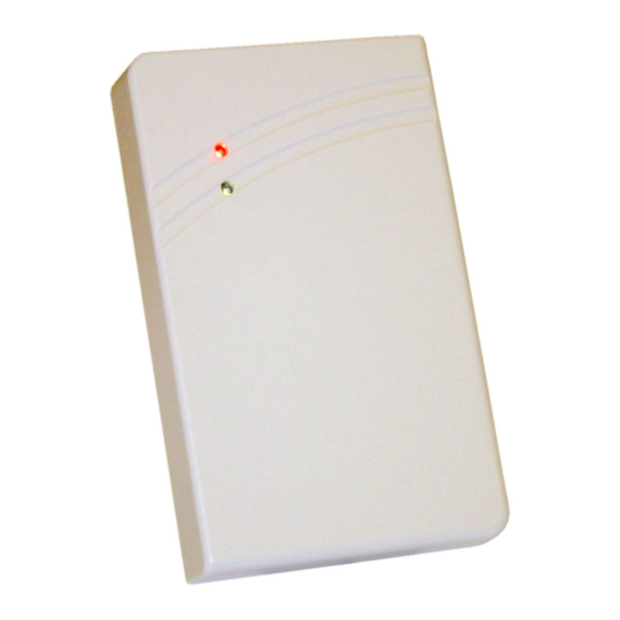
Der ID CPR.03.20-CD ist für die Montage auf ebenen, nicht leitfähigen Wänden vorgesehen. Die Konfiguration erfolgt über ConfigCard Transponder, die vor der Inbetriebnahme bequem er- stellt werden können. Technische Daten Abmessungen in Millimeter FEIG ELECTRONIC GmbH Seite 6 von 24 M60100-2de-ID-B.doc... - Page 7 1 x schaltet LED rot 1 x schaltet LED grün 1 x schaltet Beeper 1 x Hold Funktion • Schnittstelle Data/Clock Emulation von: - Magnetkarte (ISO7811-2, 5 Bit) - Wiegand • RS232-TTL Flash Ermöglicht In-circuit Firmwareupdate FEIG ELECTRONIC GmbH Seite 7 von 24 M60100-2de-ID-B.doc...
-
Page 8: Zulassung
(2) this device must accept any interference received, including interference that may cause undesired operation. Any changes or modifications not expressly approved by the party responsible for compliance could void the user's authority to operate the equipment. FEIG ELECTRONIC GmbH Seite 8 von 24 M60100-2de-ID-B.doc... -
Page 9: Installation
Verwenden Sie für die Montage auf 60 mm DIN Unterputzdosen (DIN 49 073) die beiliegenden Montageschrauben (3,2 x 25 mm). • Wählen Sie für andere Montagearten Senkkopfschrauben der Größe 3 mm, nach DIN 963 oder mit Senkkopf nach DIN 965, Kopfdurchmesser max. 5,6 mm. Montage Demontage FEIG ELECTRONIC GmbH Seite 9 von 24 M60100-2de-ID-B.doc... -
Page 10: Anschluss
+9..15 V DC green Data / Data0 white Clock / Data1 violet grey LED green brown LED red yellow Beeper blue Hold black RS232 pink RS232 TxD red/blue RS232 RxD RS232-TTL max. 3 m FEIG ELECTRONIC GmbH Seite 10 von 24 M60100-2de-ID-B.doc... -
Page 11: Konfiguration
2 x LED rot + Beep ⇒ Fehler ConfigCard wurde nicht fehlerfrei eingelesen. ⇒ Vorgang wiederholen. ⇒ Überprüfen Sie die korrekte Programmierung der ConfigCard. Hinweis: ConfigCards mit falschem AFI werden vom Leser nicht erkannt. Es erfolgt keine Signalisierung. FEIG ELECTRONIC GmbH Seite 11 von 24 M60100-2de-ID-B.doc... -
Page 12: Normalbetrieb
Aktiviert die grüne LED und deaktiviert die rote LED, solange der Eingang auf GND ge- schaltet ist. Beeper: Aktiviert den Beeper, solange der Eingang auf GND geschaltet ist. Hold: Der Leser akzeptiert keine Transponder, solange der Eingang auf GND geschaltet ist. FEIG ELECTRONIC GmbH Seite 12 von 24 M60100-2de-ID-B.doc... -
Page 13: Data-/Clock Schnittstelle
Details zu den Funktionen, Datenformaten und zum Firmwareupdate sind im Handbuch des CPR.03.20-CD (Dokument-Nr. H60100-#e-ID-B) beschrieben. Lieferumfang 1 x Gehäuseunterteil inklusive vergossener Elektronik 1 x Gehäuseoberteil 1 x Beipack (2 Schrauben 3,2x 25 mm 1 x Montageanleitung FEIG ELECTRONIC GmbH Seite 13 von 24 M60100-2de-ID-B.doc... - Page 14 FEIG ELECTRONIC call explicit attention that devices which are subject of this document are not designed with components and testing methods for a level of reliability suitable for use in or in connection with surgical implants or as critical components in any life support systems whose failure to perform can reasonably be expected to cause significant injury to a human.
- Page 15 Introduction Technical Specifications Approval ........................19 Installation Mounting ........................20 Connection........................21 Configuration .......................22 4.3.1 Default Configuration.....................22 4.3.2 Reloading the configuration...................22 Normal Operating Mode Digital Inputs........................23 Data-/Clock Interface....................24 Asynchronous Interface: RS232-TTL ................24 System Delivery Contents FEIG ELECTRONIC GmbH Page 15 of 24 M60100-2de-ID-B.doc...
- Page 16 25 cm between the device and your cardiac pace- maker and not stay in an immediate proximity of the device respective the antenna for some time. FEIG ELECTRONIC GmbH Page 16 of 24 M60100-2de-ID-B.doc...
-
Page 17: Technical Specifications
The ID CPR.03.20-CD is designed to be wall-mounted onto flat and non-conductive walls with or without a flush-mounting box. The configuration could changed while installation with a ConfigCard transponder. This ConfigCard could prepared comfortable before Installation with a separate tool. Technical Specifications Dimension's in millimeter. FEIG ELECTRONIC GmbH Page 17 of 24 M60100-2de-ID-B.doc... - Page 18 1 x switches LED green 1 x switches Beeper 1 x Hold Function Interface 1. Data/Clock Emulation: - Magnetic Stripe (ISO7811-2, 5 Bit) - Wiegand 2. RS232-TTL Flash In-circuit firmware update via RS232-TTL interface possible FEIG ELECTRONIC GmbH Page 18 of 24 M60100-2de-ID-B.doc...
-
Page 19: Approval
(2) this device must accept any interference received, including interference that may cause undesired operation. Any changes or modifications not expressly approved by the party responsible for compliance could void the user's authority to operate the equipment. FEIG ELECTRONIC GmbH Page 19 of 24 M60100-2de-ID-B.doc... -
Page 20: Installation
Use the screws provided (3.2 x 25 mm) for installation on 60 mm DIN flush-mounting boxes. • For other installation methods use 3 mm countersunk-head screws to DIN 963 or with a coun- tersunk head max. diameter of head 5.6 mm. Assembling Disassembling FEIG ELECTRONIC GmbH Page 20 of 24 M60100-2de-ID-B.doc... -
Page 21: Connection
+9..15 V DC green Data / Data0 white Clock / Data1 violet grey LED green brown LED red yellow Beeper blue Hold black RS232 pink RS232 TxD red/blue RS232 RxD RS232-TTL max. 3 m FEIG ELECTRONIC GmbH Page 21 of 24 M60100-2de-ID-B.doc... -
Page 22: Configuration
2 x LED rot + Beep ⇒ Fault ConfigCard is not read correctly. ⇒ Repeat procedure. ⇒ Check the ConfigCard for correct programming. Note: ConfigCards with incorrect AFI are not recognized by the reader. No signaling is possible FEIG ELECTRONIC GmbH Page 22 of 24 M60100-2de-ID-B.doc... -
Page 23: Digital Inputs
Activates the green LED and deactivates the red LED, as long as the input is connected to GND. Beeper: Activates the beeper LED, as long as the input is connected to GND. Hold: Will not accept a transponder, as long as the input is connected to GND. FEIG ELECTRONIC GmbH Page 23 of 24 M60100-2de-ID-B.doc... -
Page 24: Data-/Clock Interface
CPR.03.20-CD Man- ual (Document No: H60100-#e-ID-B) System Delivery Contents 1 x housing base including sealed-in electronics 1 x housing cover 1 x accessory bag (2 screws 3,2x 25 mm 1 x Mounting Instruction FEIG ELECTRONIC GmbH Page 24 of 24 M60100-2de-ID-B.doc...
Need help?
Do you have a question about the OBID ID CPR.03.20-CD and is the answer not in the manual?
Questions and answers