Page 1
H3C S1200 Switch Series Getting Started Guide New H3C Technologies Co., Ltd. http://www.h3c.com Document version: 5W100-20180626...
Page 2
The information in this document is subject to change without notice. All contents in this document, including statements, information, and recommendations, are believed to be accurate, but they are presented without warranty of any kind, express or implied. H3C shall not be liable for technical or editorial errors or omissions contained herein.
Page 3
Preface H3C S1200 Switch Series Getting Started Guide describes the appearance, installation, power-on, technical specifications, and troubleshooting of the H3C S1200 Switch Series. This preface includes the following topics about the documentation: • Audience. • Conventions. • Documentation feedback. Audience This documentation is intended for: •...
Page 4
Symbols Convention Description An alert that calls attention to important information that if not understood or followed WARNING! can result in personal injury. An alert that calls attention to important information that if not understood or followed CAUTION: can result in data loss, data corruption, or damage to hardware or software. An alert that calls attention to essential information.
Page 5
Documentation feedback You can e-mail your comments about product documentation to info@h3c.com. We appreciate your comments.
• The rack, table, or horizontal surface is sturdy enough to support the switch and its accessories. • The rack is reliably grounded. To ensure correct operation and long service life of your switch, install it in an environment that meets the requirements described in the following subsections.
Page 9
To prevent EMI, perform the following tasks: • If AC power is used, use a single-phase three-wire power receptacle with protection earth (PE) to filter interference from the power grid. • Keep the switch far away from radio transmitting stations, radar stations, and high-frequency devices.
Installing the switch WARNING! Before installing or moving the switch, remove the power cord. You can install an H3C S1200 switch in a 19-inch rack, on a horizontal surface, on a wall, or under a table. Rack mounting Wear an ESD wrist strap and make sure it makes good skin contact and is reliably grounded.
Page 11
Figure 3 Attaching Type-A mounting brackets to the rack post Figure 4 Attaching Type-B mounting brackets to the rack post...
Horizontal surface mounting IMPORTANT: • Reserve a clearance of 10 cm (3.9 in) around the chassis for heat dissipation. • Do not place heavy objects on the switch. To mount the switch on a horizontal surface: Verify that the horizontal surface is sturdy and reliably grounded. Place the switch bottom up, and clean the round holes in the chassis bottom with a dry cloth.
Page 13
Figure 7 Wall-mounting anchor kit To install the switch on a concrete wall: Drill two holes at the same height, as shown in Figure Figure 8 Hole spacing The hole depth and diameter depend on the wall anchors and screws you use. Make sure you can push the anchors to their full depth in the holes.
Align the two mounting holes in the switch chassis bottom with the two screws on the wall and hang the switch. Make sure the Ethernet ports are facing upwards or downwards and the chassis side panels are perpendicular to the ground. Figure 10 Wall mounting (1) Mounting hole in the switch chassis bottom Under-table mounting...
To mount the switch under a table: Follow the instructions on wall mounting to determine the location of screw holes to be used for under-table mounting. Align the two mounting holes in the switch chassis bottom with the two screws on the bottom of the table and hang the switch.
NOTE: • Keep the protective sleeves for future use. • The fiber ports on the S1224F Switch operate in autonegotiation mode. For the link between the switch and the peer device to operate correctly, verify that the fiber ports on the peer device also operate in autonegotiation mode.
Examine the power LED. If it is ON, the power connection is correct. Figure 15 Connecting the power adapter NOTE: H3C recommends that you ground the S1205-PWR or S1208-PWR if the PD connecting to it is grounded. The grounding cables are user supplied. Verifying the installation After you complete the installation, verify the following items: •...
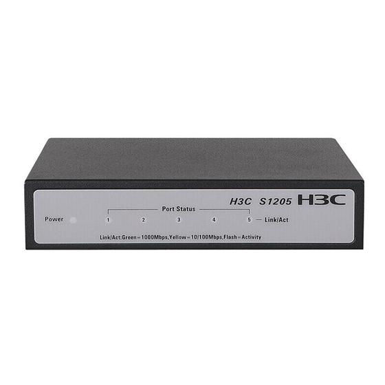
Appendix A Chassis views and technical specifications Chassis views S1205 Figure 16 S1205 front panel (1) Power LED (2) Copper port LEDs Figure 17 S1205 rear panel (1) Security slot (2) 10/100/1000BASE-T copper ports (3) DC Power receptacle S1205-PWR Figure 18 S1205-PWR front panel (1) Power LED (2) Copper port LEDs (3) PoE status LEDs...
Figure 31 S1224P-X rear panel (1) Grounding screw (2) AC power receptacle S1224-PWR Figure 32 S1224-PWR front panel (1) 10/100/1000BASE-T copper ports (1 to 12 are PoE ports) (2) PoE status LEDs (3) PoE-MAX LED (4) Copper port LEDs (5) Power LED Figure 33 S1224-PWR rear panel (1) Grounding screw (2) AC power receptacle...
DC input voltage specifications Chassis Voltage S1205 12V DC S1205-PWR 54V DC S1208 12V DC S1208-PWR 54V DC Power consumption specifications for non-PoE switches Chassis Min. power consumption Max. power consumption S1205 S1208 4.5 W S1216 6.8 W 12 W S1224 16 W S1224F...
Appendix B LEDs Power LED Table 5 Power LED description Status Description Steady green The switch is powered on and the power supply is operating correctly. The switch is powered on and is performing the self-test. The switch is faulty if the Flashing green LED flashes green for five seconds.
Table 10 PoE-MAX LED description(S1224-PWR) Status Description Steady yellow The PoE power reaches the guard band (104 W to 124 W). The PoE power does not reach 104 W. NOTE: A port with a smaller port ID has a higher priority for getting power. When the PoE power reaches the guard band and a new port requires power, the switch compares the port IDs and performs one of the following actions: •...
Appendix C Troubleshooting Table 13 describes the troubleshooting methods for common issues that you might encounter while using and managing the switch. If a problem persists, contact H3C Support. Table 13 Troubleshooting methods Symptom Troubleshooting method Verify that the correct power source is used and the power cords are correctly connected.
Index A C D E F I P S T AC input voltage specifications,17 Ports and interface card slots,17 Power consumption specifications for non-PoE switches,18 Chassis dimensions and weights,16 Power consumption specifications for PoE Cleanliness,2 switches,18 Connecting network cable,9 Power LED,19 Connecting the AC power cord,10...
Need help?
Do you have a question about the S1200 Series and is the answer not in the manual?
Questions and answers