Table of Contents
Advertisement
Quick Links
Advertisement
Chapters
Table of Contents

Related Manuals for Ovlac SS Series


Summary of Contents for Ovlac SS Series
- Page 1 2016 OPERATING INSTRUCIONS AND SPARE SS - SL PARTS...
-
Page 2: Table Of Contents
This handbook describes the use, maintenance instructions 1. Safety provisions ..........3 and spare parts supplied for the indicated plough. 2. Description and technical data ......5 The farming implement known as “plough“ is designed to 3. Protection systems ..........7 work the soil, linked to a tractor with lift and universal 3-point 4. -
Page 3: Safety Provisions
SAFETY PROVISIONS 12.- Take the utmost care during the plough coupling and release 1.- Comply with the instructions given by the danger signals exposed phases. in this handbook (Fig.1) and affixed to the plough itself. 13.- Never ever leave the driving seat whilst the tractor is moving. 2.- Operations and adjustments to the implement must always be carried out when the engine is off and the tractor braked. - Page 4 Be prepared in case of emergency (Fig.1) WARNING Have near a first aid kit and an extinguisher. Write down the telephone numbers of doctors, ambulances and firemen and keep them near the Thoroughly read the manual before starting to work telephone.
-
Page 5: Description And Technical Data
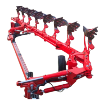
DESCRIPTION AND DATA TECHNICAL 1. HEADSTOCK 2. IDENTIFICATION PLATE IDENTIFICATION PLATE (2) 3. DRAW FRAME 4. EYE PIECE 5. TURNOVER CONNECTION 6. ON-LAND ARTICULATION 7. FRAME REMARK: The construction number 8. TELESCOPIC FRAME that is engraved in the identification 9. FRONT WHEEL plate must be coincident with the 10. - Page 6 TECHNICAL FEATURES SS - SL UNDERBEAM MODEL WORKING WIDTH (CM) POINT TO POINT CLEARANCE WEIGHT APROX (KG) CLEARANCE SLF-5 16"-18"-20"-22" 72/78/105 100-105 2520 SLF-6 16"-18"-20"-22" 72/78/105 100-105 2715 SLF-7 16"-18"-20"-22" 72/78/105 100-105 2910 SLF-8 16"-18"-20"-22" 72/78/105 100-105 3920 SSF-5 12"-20" 72/78/105 100-105 2910...
-
Page 7: Protection Systems
PROTECTION SYSTEMS The Auto Reset protection systems (leaf spring or hydraulic) SHEAR BOLT Protection: In the SSF and SLF models, work automatically. When the share meets an obstacle the beam protection is achieved by means of shear bolts (Fig.2). When the trips up thus overcoming the obstacle and then returns back to its share point meets an obstacle, the shear bolt breaks and permits original position with no need to stop the tractor. - Page 8 Once the working pressure is set, close valves. Note: The auto Reset systems from OVLAC are set at the factory for average conditions. In order to minimize impacts on both the tractor and the plough, we recommend to work at the lowest possible pressure.
-
Page 9: Set To Work
4. SET TO WORK 4.1 ATTACHING THE PLOUGHT Before attaching the plough check the following points: The lift rods of the tractor must be set to the same length and height. The wheels of the tractor must have the same pressure and it must be set according to manufacturer´s instructions. -
Page 10: Hydraulic Connections
To detach proceed as follows: Lower the front part of the plough and act on the wheel so the tractor is lowered with the coupling bar in a horizontal position. In this way detaching as well as the next attaching will be much easier. -
Page 11: Moulboards
4.3 MOULBOARDS 4.4 FIRST FURROW WIDTH ADJUSTMENT Before starting work, the paint on the mouldboards should The first furrow width is adjusted hydraulically by means of the be removed to avoid that the soil remains adhered. In order to cylinder A (Fig.11). The longer the ram, the wider the first furrow. ease this operation, a special peel-off paint is applied at the factory. -
Page 12: Alignment
4.5 ALLIGNMENT 4.7 WORKING DEPTH The working depth is adjusted hydraulically by means of the cylinder C During work, the plough must run straight and parallel to the working (Fig.13). The maximum working depth is adjusted by means of nut D on direction. -
Page 13: Working Width
4.8 WORKING WIDTH The "S" series (SSF, SSB and SSH) features the OVLAC exclusive system to adjust hydraulically the furrow width – Varilabor - which allows to choose any working width between 12" (30cm) and 21" (53 cm) by means of the cylinder A (Fig.14). The direction of the wheel is adjusted automatically. -
Page 14: Dump
4.9 TURNOVER SYSTEM 4.10 OTHER ADJUSTMENTS The turning of the plow is achieved by acting on the telescopic Check that the beams work vertically with respect to the field. To hydraulic cylinders E (Fig.17). achieve this, make sure that the lifting arms of the tractor are set at the same length and act on the stop bolts A below the turn over rams (Fig.18) Fig.17 Fig.18... -
Page 15: Transport And Parking
TRANSPORT AND PARKING The stand P (Fig.20) guarantees a steady position when the This plough is transported in “butterfly position”. The valves V plough is parked. When parking the plough make sure that the locking pin of the stand is placed in the right hole so that he draw must be closed so that the turn over mechanism is locked (Fig.19). -
Page 16: Maintenence
6. MAINTENANCE Retighten all bolts and nuts after the first 8 hours of work, specially Take care of the leaks of high pressure the ones of mouldboards, shares and points. Henceforth, check every 100 The fluids that escape of the system can have as much force that hours of work. - Page 17 MAINTENANCE PLAN The points marked in Fig 21 must be greased with the following periodicity: 1- every 10 working hours 2- every 50 working hours 3- every 100 working hours As a general rule, all of these points should be greased before and after every season.
-
Page 18: Optional Equipment
6. OPTIONAL EQUIPMENT The Ploughts SS-SL Ovlac can be equipped with: 6.1 Disc coulters (Fig.22). 6.2 Cover Boards (Fig.23). 6.3 Slatted moulboards (Fig.24). 6.4 Landslide extension (Fig.25) 6.5 Skimboards (Fig.26). Fig.24 Fig.26 Fig.22 Fig.25 Fig.23... -
Page 19: Spare Parts
CONTENT HEADSTOCK ................. 20 8. SPARE PARTS TURNOVER CONNECTION ..........24 FOLK ..................26 Spare parts should always be ordered from your dealer and should always include the following indications: FRAME SS ................28 FRAME SL ................32 - Type, model and serial number of the plough. These data are punched on the identification plate with which every plough is equipped. -
Page 20: Headstock
HEADSTOCK... - Page 21 HEADSTOCK REFERENCIA DESCRIPCIÓN 15010901 TUERCA EJE CABEZAL 120 (D/06) 53000004 ENGRASADOR AC° DIN-71412 8*125 53000450 JUNTA TORICA 160-3 60000047 TORN.EXAG.DIN-933 10* 35 8.8 ZINC. 60000140 TUER.AUTO.DIN-980 10 8.8 ZINC. 60000218 TORN.ALLEN DIN-913 12* 16 12.9 61000036 ARAND.ESTANDAR-A 32 ZINC. 62000004 PASADOR ANILLA 10 ZINC.
- Page 22 TURNOVER CONNECTION...
- Page 23 TURNOVER CONNECTION REFERENCIA DESCRIPCIÓN REFERENCIA DESCRIPCIÓN 53000004 ENGRASADOR AC° DIN-71412 8*125 95023972 BULON D=50*307mm.SOP.GIRO BAST.SSN 53000022 ABRAZ.DOBLE D=19mm. 1D19PP 95026900 ARAND.P/BULON GIRO BASTIDOR 53000025 M.TUBO ACERO D=12*9mm.ZINC. 95056901 BULON D=50*319mm.CONEX.VOLTEO SS 53000105 ENGRASADOR MT-503 10*150 95056902 BULON D=34,8*100mm.CILIND.VOLTEO SS + DACROMET 53000200 PLACA RFZO.AB.DOBLE 19 GD3D 95056940 CONEX.VOLTEO SSN 60000015 TORN.EXAG.DIN-933 8* 25 8.8 ZINC.
-
Page 24: Turnover Connection
TURNOVER CONNECTION INSIDE/OUTSIDE GROOVE... - Page 25 TURNOVER CONNECTION INSIDE/OUTSIDE GROOVE REFERENCIA DESCRIPCIÓN REFERENCIA DESCRIPCIÓN 53000004 ENGRASADOR AC° DIN-71412 8*125 95023972 BULON D=50*307mm.SOP.GIRO BAST.SSN 53000022 ABRAZ.DOBLE D=19mm. 1D19PP 95026900 ARAND.P/BULON GIRO BASTIDOR 53000025 M.TUBO ACERO D=12*9mm.ZINC. 95056901 BULON D=50*319mm.CONEX.VOLTEO SS 53000105 ENGRASADOR MT-503 10*150 95056902 BULON D=34,8*100mm.CILIND.VOLTEO SS + DACROMET 53000200 PLACA RFZO.AB.DOBLE 19 GD3D 95059902 BULON D=50*307mm.LANZA TIRO SS 60000015 TORN.EXAG.DIN-933 8* 25 8.8 ZINC.
-
Page 26: Folk
FOLK... - Page 27 FOLK REFERENCIA DESCRIPCIÓN 53000004 ENGRASADOR AC° DIN-71412 8*125 62000004 PASADOR ANILLA 10 ZINC. 62000011 PASADOR ELAST.DIN-1481 8* 50 ZINC. 62000030 PASADOR ELAST.DIN-1481 10* 80 ZINC. 95025911 BULON D=50*322mm.GIRO BAST.SS FS 95026900 ARAND.P/BULON GIRO BASTIDOR 95056903 BULON D=34,8*295mm.HORQUILLA SS FS 95063004 TAPON HORQ.SS 95066904 BULON D=29,7*112mm.CILIND.APERT SS...
-
Page 28: Frame Ss
FRAME SS... - Page 29 FRAME SS REFERENCIA DESCRIPCIÓN REFERENCIA DESCRIPCIÓN 9000038 TAPON GOMA 150*150*10mm. 60000138 TUER.AUTO.DIN-980 1"SAE 10.9 ZINC. 9000097 TAPON GOMA 80* 50* 6mm. 60000146 TUER.AUTO.DIN-980 20 10.9 ZINC. 15021992 BIELA S-2-100 APERTURA SSN 60000157 TUER.EXAG.DIN-934 12 8.8 ZINC. 15023912 CASQ.GIRO BAST.SN-150 C/VARILLAS 60000218 TORN.ALLEN DIN-913 12* 16 12.9 15023921 CASQ.GIRO BAST.SSN C/VARILLAS 60000230 TORN.EXAG.C/LAR.20*200 12.9...
- Page 30 FRAME SS PLACA SUPERIOR PLACA INFERIOR REFERENCIA DESCRIPCIÓN REFERENCIA DESCRIPCIÓN 15023970 PLACA SUP.SOP.GIRO BAST.SSN-100 15023971 PLACA INF.SOP.GIRO BAST.SSN-100 15023980 PLACA SUP.SOP.GIRO BAST.SSN-5-100 15023981 PLACA INF.SOP.GIRO BAST.SSN-5-100 15023982 PLACA SUP.SOP.GIRO BAST.SSN-7-100 15023983 PLACA INF.SOP.GIRO BAST.SSN-7-100 15123906 PLACA SUP.SOP.GIRO BAST.SSN-6-105 FS 15123916 PLACA INF.SOP.GIRO BAST.SSN-6-105 FS 15123907 PLACA SUP.SOP.GIRO BAST.SSN-7-105 FS 15123917 PLACA INF.SOP.GIRO BAST.SSN-7-105 FS 15123970 PLACA SUP.SOP.GIRO BAST.SSN-6-105...
- Page 31 FRAME SS DOUBLE MODULE REFERENCIA DESCRIPCIÓN 15031920 PLACA SOP.GIRO RDA.SSN-105 53000004 ENGRASADOR AC° DIN-71412 8*125 60000112 TORN.EXAG.DIN-931 20*200 8.8 60000127 TORN.EXAG.DIN-931 20*190 8.8 60000146 TUER.AUTO.DIN-980 20 10.9 ZINC. 60000230 TORN.EXAG.C/LAR.20*200 12.9 60000395 TUER.AUTO.DIN-980 20 8.8 BAJA ZINC.
-
Page 32: Frame Sl
FRAME SL... - Page 33 FRAME SL REFERENCIA DESCRIPCIÓN REFERENCIA DESCRIPCIÓN 9000038 TAPON GOMA 150*150*10mm. 60000040 TORN.EXAG.DIN-931 20*230 8.8 15023911 CASQ.GIRO BAST.SN-120 C/VARILLAS 60000112 TORN.EXAG.DIN-931 20*200 8.8 15023912 CASQ.GIRO BAST.SN-150 C/VARILLAS 60000146 TUER.AUTO.DIN-980 20 10.9 ZINC. 15023970 PLACA SUP.SOP.GIRO BAST.SSN-100 60000230 TORN.EXAG.C/LAR.20*200 12.9 15023971 PLACA INF.SOP.GIRO BAST.SSN-100 60000231 TORN.EXAG.C/LAR.20*225 12.9 15030906 BAST.SSN-6-100-AMP.
- Page 34 FRAME SL DOUBLE MODULE REFERENCIA DESCRIPCIÓN 15023911 CASQ.GIRO BAST.SN-120 C/VARILLAS 15031920 PLACA SOP.GIRO RDA.SSN-105 53000004 ENGRASADOR AC° DIN-71412 8*125 60000112 TORN.EXAG.DIN-931 20*200 8.8 60000146 TUER.AUTO.DIN-980 20 10.9 ZINC. 60000230 TORN.EXAG.C/LAR.20*200 12.9 60000231 TORN.EXAG.C/LAR.20*225 12.9 95011920 CONTRATUERCA EJE CABEZAL 110 (D-07)/120/150...
-
Page 35: Additional Body
ADDITIONAL BODY... - Page 36 ADDITIONAL BODY REFERENCIA DESCRIPCIÓN REFERENCIA DESCRIPCIÓN 9000038 TAPON GOMA 150*150*10mm. 16019971 BAST.SHN-1-105-(150) 9000097 TAPON GOMA 80* 50* 6mm 16030901 BAST.SSHN-1-100 15019971 BAST.SN-1-105-(150) 16030911 BAST.SSHN-1-100-AMP. 15021982 BIELA S-2-100 SSN.(MODULO) 16131911 BAST.SSHN-1-105-AMP. 15021993 BIELA S-3-100 SSN.(MODULO DOBLE) 53000004 ENGRASADOR AC° DIN-71412 8*125 15022981 BIELA S-1-100 SSN.(2°...
-
Page 37: Varywidth System
VARYWIDTH SYSTEM... - Page 38 VARYWIDTH SYSTEM REFERENCIA DESCRIPCIÓN REFERENCIA DESCRIPCIÓN 51000062 CILIND.VOLTEO 40/70/230 ROT.D=35/30 53000086 PLACA RFZO.AB.DOBLE 12 GD1D 52000001 VALV.BLOQUEO ZINC.12 VBD38 53000121 LATIG.R2-3/8* 500mm.MT-12/MT-12 53000001 TORNILLO SIMPLE 3/8 4022 53000122 LATIG.R2-3/8*2150mm.MF-1/2/MT-12 53000006 JUNTA METAL/GOMA 1/2" 11603 53000145 LATIG.R2-3/8*1250mm.OR-3/8/MT-12 53000007 JUNTA METAL/GOMA 3/8" 11602 53000146 LATIG.R2-3/8*1290mm.CTL-3/8/MT-12 53000015 UNION MACHO 3/8...
-
Page 39: Telescopic Frame
TELESCOPIC FRAME... - Page 40 TELESCOPIC FRAME REFERENCIA DESCRIPCIÓN REFERENCIA DESCRIPCIÓN 51000061 CILIND.VOLTEO 40/95/300 ROT.D=40/35 95023971 BULON D=50*307mm.SOP.GIRO BAST.SS 53000004 ENGRASADOR AC° DIN-71412 8*125 95026900 ARAND.P/BULON GIRO BASTIDOR 53000027 ABRAZ.DOBLE D=12mm. 1D12PP 95054902 BULON D=39,8*110mm.CILIND.BAST.PPAL.SSN 53000074 ENGRASADOR MT-506 45° 8*125 95054940 BAST.PPAL.SSN 53000086 PLACA RFZO.AB.DOBLE 12 GD1D 95054945 BAST.PPAL.SSN-5 53000148 ABRAZ.SIMPLE D=18mm.
-
Page 41: Hydraulic Wheel
HYDRAULIC WHEEL... - Page 42 HYDRAULIC WHEEL REFERENCIA DESCRIPCIÓN REFERENCIA DESCRIPCIÓN 15010900 TUERCA EJE CABEZAL 110 (D/07) 65000016 PASADOR FIJACION D= 7,5mm. 51000043 CILIND.ELEV.RDA.C/TCA.50/110/150 SS 95009981 ARAND.POST.110 (D/07) 53000004 ENGRASADOR AC° DIN-71412 8*125 95011920 CONTRATUERCA EJE CABEZAL 110 (D-07)/120/150 53000025 M.TUBO ACERO D=12*9mm.ZINC.. 95025936 BULON D=50*402mm.HORQUILLA SS (D/14) 53000025 M.TUBO ACERO D=12*9mm.ZINC..
-
Page 43: Advanced Wheel
ADVANCED WHEEL... - Page 44 ADVANCED WHEEL REFERENCIA DESCRIPCIÓN 53002960 BRAZO RDA.NEUM(608*205/685*260) AVZD. 53002961 BRAZO RDA.NEUM(608*205/685*260) AVZD.D/85 55010971 SOP.RDA.AVZD.L (D/13) 55013910 EXCENTRICA RDA.C/T (D/02) 55017940 BULON D=25*116mm.TOPE RDA.C/T 60000326 TUER.BAJA DIN-936 30/200 8.8 ZINC. 60000355 TUER.TOPE VOLTEO 30/200 8.8 ZINC. 61000031 ARAND.STANDAR S/BISEL CL-26 ZINC.(50x27x3) 62000010 PASADOR ELAST.DIN-1481 8* 40 ZINC.
- Page 45 ASSEMBLY ADVANCED WHEEL SS FS...
- Page 46 ASSEMBLY ADVANCED WHEEL SS FS REFERENCIA DESCRIPCIÓN 15023902 CASQ.GIRO BAST.SN-150 15027910 SOP.ARTIC.CAMBA SSBN 15027990 SOP.ARTIC.CAMBA/RDA.DELANTERA SSBN 15121972 BIELA S-2-105 SSN FS. 15121973 BIELA S-3-105 SSN FS. 15123906 PLACA SUP.SOP.GIRO BAST.SSN-6-105 FS 15123907 PLACA SUP.SOP.GIRO BAST.SSN-7-105 FS 15123916 PLACA INF.SOP.GIRO BAST.SSN-6-105 FS 15123917 PLACA INF.SOP.GIRO BAST.SSN-7-105 FS 17027990...
- Page 47 ASSEMBLY ADVANCED WHEEL SL FS REFERENCIA DESCRIPCIÓN 60000114 TORN.EXAG.DIN-931 20*220 8.8 ZINC. 55010971 SOP.RDA.AVZD.L (D/13) 60000146 TUER.AUTO.DIN-980 20 10.9 ZINC. 60000331 TORN.EXAG.DIN-933 20* 50 8.8 ZINC. 15123917 PLACA INF.SOP.GIRO BAST.SSN-7-105 FS 15123907 PLACA SUP.SOP.GIRO BAST.SSN-7-105 FS 18029995 SOP.ARTIC.CAMBA/RDA.DELANTERA SLFN...
-
Page 48: Beam Support
BEAM SUPPORT SF - LF REFERENCIA DESCRIPCIÓN 17030900 CAMBA SFN 30mm. (H/13) 17030976 CAMBA SFN 30mm 75cm.DESPEJE (D/13) 17030986 CAMBA SFN 30mm.85cm.DESPEJE (D/13) 17031900 PLACA PORTACAMBA EXT.SFN 60000021 TORN.EXAG.C/LAR.1"* 85 SAE 12.9 60000099 TORN.EXAG.C/LAR.20* 80 10.9 60000100 TORN.EXAG.DIN-931 20* 70 8.8 60000138 TUER.AUTO.DIN-980 1"SAE 10.9 ZINC. - Page 49 BEAM SUPPORT SB – LB Until 2015...
- Page 50 BEAM SUPPORT SB – LB Until 2015 REFERENCIA DESCRIPCIÓN REFERENCIA DESCRIPCIÓN 15033950 BRAZO PORTACAMBA SB (D/13) 62000010 PASADOR ELAST.DIN-1481 8* 40 ZINC. 53000004 ENGRASADOR AC° DIN-71412 8*125 62000032 PASADOR ELAST.DIN-1481 3* 30 ZINC. 60000052 TORN.EXAG.DIN-931 10* 55 10.9 ZINC. 90031900 BARRA TENSORA 60000056 TORN.EXAG.DIN-933 12* 20 12.9 90032900 BULON D=25* 70mm.TIRO BARRA TENSORA 60000098 TORN.EXAG.DIN-931 20* 60 8.8...
- Page 51 BEAM SUPPORT SB – LB AFTER 2015...
- Page 52 BEAM SUPPORT SB – LB AFTER 2015 REFERENCIA DESCRIPCIÓN REFERENCIA DESCRIPCIÓN 15033951 BRAZO PORTACAMBA SB (D/15) 62000008 PASADOR ELAST.DIN-1481 5* 30 ZINC. 53000004 ENGRASADOR AC° DIN-71412 8*125 62000010 PASADOR ELAST.DIN-1481 8* 40 ZINC. 60000052 TORN.EXAG.DIN-931 10* 55 10.9 ZINC. 62000032 PASADOR ELAST.DIN-1481 3* 30 ZINC. 60000056 TORN.EXAG.DIN-933 12* 20 12.9 90031900 BARRA TENSORA 60000098 TORN.EXAG.DIN-931 20* 60 8.8...
- Page 53 BEAM SUPPORT SH – LH UNTIL 2015...
- Page 54 BEAM SUPPORT SH – LH UNTIL 2015 REFERENCIA DESCRIPCIÓN 15033900 BRAZO PORTACAMBA SH (D/13) 51000007 CILIND.TRACCION 110/36/90 AR 51000008 CILIND.TRACCION 100/36/90 AR 53000001 TORNILLO SIMPLE 3/8 4022 53000007 JUNTA METAL/GOMA 3/8" 11602 53000026 PLACA RFZO.AB.SIMPLE 20 53000031 LATIG.R2-3/8*1300mm.OR-3/8/TL-18 53000041 ABRAZ.SIMPLE D=19mm. 319PP 53000095 LATIG.R2-3/8*1950mm.OR-3/8/TL-18 60000056 TORN.EXAG.DIN-933 12* 20 12.9 60000098 TORN.EXAG.DIN-931 20* 60 8.8...
- Page 55 BEAM SUPPORT SH – LH AFTER 2015...
- Page 56 BEAM SUPPORT SH – LH AFTER 2015 REFERENCIA DESCRIPCIÓN REFERENCIA DESCRIPCIÓN 15033900 BRAZO PORTACAMBA SH (D/13) 60000138 TUER.AUTO.DIN-980 1"SAE 10.9 ZINC. 15033902 CASQ.D= 45/20,5*26mm.PORTACAMBA SB 60000143 TUER.AUTO.DIN-980 16 8.8 ZINC. 51000007 CILIND.TRACCION 110/36/90 AR 60000146 TUER.AUTO.DIN-980 20 10.9 ZINC. 51000008 CILIND.TRACCION 100/36/90 AR 60000180 TORN.EXAG.DIN-931 6* 40 8.8 ZINC.
-
Page 57: Hydroneumatic System
HYDROPNEUMATIC SYSTEM... - Page 58 53000238 REDUCCION MACHO-TUERCA LOCA 1/4-3/8 4322 53000036 TE UNION IGUAL 12 T12-L 53000502 ABRAZ.ACUMULADOR 80/88 MPC 53000037 MANOM.GLIC.63 0-315 (MOD.OVLAC) 263R0-315 60000015 TORN.EXAG.DIN-933 8* 25 8.8 ZINC. 53000041 ABRAZ.SIMPLE D=19mm. 319PP 60000186 TORN.EXAG.DIN-931 6* 50 8.8 ZINC. 53000045 UNION REDUCCION 3/8-1/2 4072 60000187 TORN.EXAG.DIN-931 6* 60 8.8 ZINC.
- Page 59 HYDRAULIC TUBE DETAIL 100 REFERENCIA DESCRIPCIÓN 53000031 LATIG.R2-3/8*1300mm.OR-3/8/TL-18 53000043 LATIG.R2-3/8* 830mm.TL-18/TL-18 53000094 LATIG.R2-3/8* 965mm.TL-18/TL-18 53000095 LATIG.R2-3/8*1950mm.OR-3/8/TL-18 53000151 LATIG.R2-3/8* 885mm.TL-18/TL-18 53000152 LATIG.R2-3/8* 420mm.TL/TL-18 53000239 LATIG.R2-3/8* 420mm.TL-3/8/TL-18...
- Page 60 HYDRAULIC TUBE DETAIL 105 REFERENCIA DESCRIPCIÓN 53000031 LATIG.R2-3/8*1300mm.OR-3/8/TL-18 53000042 LATIG.R2-3/8* 930mm.TL-18/TL-18 53000043 LATIG.R2-3/8* 830mm.TL-18/TL-18 53000095 LATIG.R2-3/8*1950mm.OR-3/8/TL-18 53000152 LATIG.R2-3/8* 420mm.TL/TL-18 53000239 LATIG.R2-3/8* 420mm.TL-3/8/TL-18 53000242 LATIG.R2-3/8*1020mm.TL-18/TL-18...
- Page 61 HYDRAULIC TUBE OF LOAD REFERENCIA DESCRIPCIÓN 53000006 JUNTA METAL/GOMA 1/2" 11603 53000037 MANOM.GLIC.63 0-315 (MOD.OVLAC) 263R0-315 53000277 PROTECTOR E.R.MACHO 1/2" AZUL 5029-4PB 53000364 UNION MACHO/HEMBRA 1/2 GAS LEK-S-816-21-50 53000414 TE M/M 1/2 GAS (CUADRADO) LEK-S-955-21 53000415 TOMA PRESION 1/2 GAS...
-
Page 62: Hydraulic Rollover System
HYDRAULIC ROLLOVER SYSTEM REFERENCIA DESCRIPCIÓN 51000213 CILIND.VOLTEO TELESC.2 EXP.60/100/470 SS 53000006 JUNTA METAL/GOMA 1/2" 11603 53000007 JUNTA METAL/GOMA 3/8" 11602 53000015 UNION MACHO 3/8 4062 53000021 PROTECTOR E.R.MACHO 1/2" ROJO 5029-4PR 53000048 UNION MACHO BSP 3/8-12 GE12-L 53000059 ESFERICO 3/8" TUBO 12mm.CORTO 4002E 53000075 TORNILLO SIMPLE 3/8 REDUCTOR 4022-T 53000123 LATIG.R2-3/8*3700mm.MF-1/2/TL-3/8 53000128 VALV.ESFERA 2/2 3/8... -
Page 63: Hydraulic Folk System
HYDRAULIC FOLK SYSTEM REFERENCIA DESCRIPCIÓN 51000062 CILIND.VOLTEO 40/70/230 ROT.D=35/30 52000001 VALV.BLOQUEO ZINC.12 VBD38 53000001 TORNILLO SIMPLE 3/8 4022 53000006 JUNTA METAL/GOMA 1/2" 11603 53000007 JUNTA METAL/GOMA 3/8" 11602 53000015 UNION MACHO 3/8 4062 53000059 ESFERICO 3/8" TUBO 12mm.LG=40 4002E 53000061 ESFERICO 3/8" TUBO 12mm.LG=205 4002E-205 53000075 TORNILLO SIMPLE 3/8 REDUCTOR 4022-T 53000473 LATIG.R2-3/8*4050mm.MF-1/2/OR-3/8 53000474 LATIG.R2-3/8*4100mm.MF-1/2/CTL-3/8... -
Page 64: Hydraulic Varywidth System
HYDRAULIC VARYWIDTH SYSTEM... - Page 65 HYDRAULIC VARYWIDTH SYSTEM REFERENCIA DESCRIPCIÓN REFERENCIA DESCRIPCIÓN 51000062 CILIND.VOLTEO 40/70/230 ROT.D=35/30 53000145 LATIG.R2-3/8*1250mm.OR-3/8/MT-12 52000001 VALV.BLOQUEO ZINC.12 VBD38 53000146 LATIG.R2-3/8*1290mm.CTL-3/8/MT-12 53000001 TORNILLO SIMPLE 3/8 4022 53000260 TUERCA M18*1,5 C/BICONO D12L M12-L PSR12LX 53000006 JUNTA METAL/GOMA 1/2" 11603 53000278 PROTECTOR E.R.MACHO 1/2" AMARILLO 5029-4PY 53000007 JUNTA METAL/GOMA 3/8"...
-
Page 66: Hydraulic Telescopic System
HYDRAULIC TELESCOPIC SYSTEM... - Page 67 HYDRAULIC TELESCOPIC SYSTEM REFERENCIA DESCRIPCIÓN 15018906 CASQ. D=45/35*8 SEP.APERT.CICRO 52000001 VALV.BLOQUEO ZINC.12 VBD38 53000001 TORNILLO SIMPLE 3/8 4022 53000006 JUNTA METAL/GOMA 1/2" 11603 53000007 JUNTA METAL/GOMA 3/8" 11602 53000015 UNION MACHO 3/8 4062 53000025 M.TUBO ACERO D=12*9mm.ZINC.. 53000027 ABRAZ.DOBLE D=12mm. 1D12PP 53000075 TORNILLO SIMPLE 3/8 REDUCTOR 4022-T 53000086 PLACA RFZO.AB.DOBLE 12 GD1D...
-
Page 68: Hydraulic Whell System
HYDRAULIC WHEEL SYSTEM... - Page 69 HYDRAULIC WHEEL SYSTEM REFERENCIA DESCRIPCIÓN 51000043 CILIND.ELEV.RDA.C/TCA.50/110/150 SS 52000001 VALV.BLOQUEO ZINC.12 VBD38 53000001 TORNILLO SIMPLE 3/8 4022 53000006 JUNTA METAL/GOMA 1/2" 11603 53000007 JUNTA METAL/GOMA 3/8" 11602 53000015 UNION MACHO 3/8 4062 53000017 LATIG.R2-3/8* 500mm.TL/CTL-3/8 53000025 M.TUBO ACERO D=12*9mm.ZINC.. 53000055 ESFERICO ROSCADO 3/8 4012 53000075 TORNILLO SIMPLE 3/8 REDUCTOR 4022-T 53000121 LATIG.R2-3/8* 500mm.MT-12/MT-12...
-
Page 70: Accumulator Assembly Wheel
ACCUMULATOR ASSEMBLY WHEEL... - Page 71 ACCUMULATOR ASSEMBLY WHEEL REFERENCIA DESCRIPCIÓN 51000118 ACUMULADOR PISTON PO10A34N1-AC RAL-6029 53000006 JUNTA METAL/GOMA 1/2" 11603 53000045 UNION REDUCCION 3/8-1/2 4072 53000047 TE M/M C/TCA.LOCA LAT.3/8 4402 53000093 JUNTA METAL GOMA 1/4 11601 53000108 LATIG.R2-3/8* 900mm.TL/CTL-3/8 53000235 UNION REDUCCION 1/4-3/8 4071 53000238 REDUCCION MACHO-TUERCA LOCA 1/4-3/8 4322 53000299 REGULADOR CAUDAL POMO UNID.1/4 9F400S 53000502 ABRAZ.ACUMULADOR 80/88 MPC...
- Page 72 HYDRAULIC TUBE REFERENCIA DESCRIPCIÓN 53000022 ABRAZ.DOBLE D=19mm. 1D19PP 53000027 ABRAZ.DOBLE D=12mm. 1D12PP 53000086 PLACA RFZO.AB.DOBLE 12 GD1D 60000180 TORN.EXAG.DIN-931 6* 40 8.8 ZINC. 60000201 TORN.EXAG.DIN-931 8* 45 8.8 ZINC. 60000204 TORN.EXAG.DIN-931 8*120 8.8 ZINC. 60000254 TORN.EXAG.DIN-931 8*100 8.8 ZINC. 95073905 SOPORTE LATIG.SS...
-
Page 73: Supl. Electro Valve
SUPL. ELECTRO VALVE... - Page 74 SUPL. ELECTRO VALVE REFERENCIA DESCRIPCIÓN 51000048 DISTRIBUIDOR 6 VIAS M9278/12 51000059 M.CABLE H07RN-F GOMA 2x1,5MM. 51000209 ENCHUFE PLASTICO MACHO 3PIN/2P FIJ 225282 53000006 JUNTA METAL/GOMA 1/2" 11603 53000007 JUNTA METAL/GOMA 3/8" 11602 53000020 LATIG.R2-3/8*1800mm.MF-1/2/MF-3/8 53000022 ABRAZ.DOBLE D=19mm. 1D19PP 53000025 M.TUBO ACERO D=12*9mm.ZINC.. 53000025 M.TUBO ACERO D=12*9mm.ZINC..
- Page 75 SUPL. ELECTRO VALVE...
-
Page 76: Bodies
BODIES V-97 / V-34 / V-90 / V-74... - Page 77 BODIES V-97 / V-34 / V-90 / V-74 REFERENCIA DESCRIPCIÓN REFERENCIA DESCRIPCIÓN 15045900 PORTA-REJAS DCH. V-97/ V-34 (D/04) 64000033 PUNTA REJA 1365-D 65x12mm. 15046900 PORTA-REJAS IZQD. V-97/ V-34 (D/04) 64000034 PUNTA REJA 1365-I 65x12mm. 15074900 TENSOR V-34 CORTO DCH.(D/04) 64000044 COSTANERA CORTA 2338-CAV-BAR 15074910 TENSOR V-97 CORTO DCH.(D/04) 64000045 COSTANERA LARGA 2339-CAV-BAR 15074920 TENSOR V-90 CORTO DCH.
- Page 78 BODIES V-40...
- Page 79 BODIES V-40 REFERENCIA DESCRIPCIÓN 17045900 PORTA-REJAS DCH. V-40 (D/04) 17047900 PORTA-REJAS IZQ. V-40 (D/04) 17094902 TENSOR V-40 CORTO DCH.(D/04) 17094903 TENSOR V-40 CORTO IZQD.(D/04) 60000019 TORN.ARADO C/OV/934 12*36 12.9 60000023 TORN.ARADO C/OV/934 12*42 12.9 60000025 TORN.ARADO C/OV/934 14*35 12.9 60000139 TORN.ARADO 2TET/934 12*35 8.8 ZINC. 60000165 TUER.EXAG.DIN-934 22 8.8 ZINC.
- Page 80 BODIES LOV...
- Page 81 BODIES LOV REFERENCIA DESCRIPCIÓN REFERENCIA DESCRIPCIÓN 60000014 TORN.ARADO C/OV/934 12*33 12.9 64000184 CORTANTE I-LK 3492891 60000019 TORN.ARADO C/OV/934 12*36 12.9 64000335 PUNTA REJA I LOV 15mm. 60000080 TORN.EXAG.DIN-931 16* 60 8.8 ZINC. 64000453 LAMINA 2-D (D/09-11) 60000098 TORN.EXAG.DIN-931 20* 60 8.8 64000454 LAMINA 2-I (D/09-11) 60000100 TORN.EXAG.DIN-931 20* 70 8.8 64000455 LAMINA 3-D (D/09-11)
- Page 82 BODIES V-PLASTIC...
- Page 83 BODIES V-PLASTIC REFERENCIA DESCRIPCIÓN 64000044 COSTANERA CORTA 2338-CAV-BAR 64000045 COSTANERA LARGA 2339-CAV-BAR 60000019 TORN.ARADO C/OV/934 12*36 12.9 60000165 TUER.EXAG.DIN-934 22 8.8 ZINC. 15045900 PORTA-REJAS DCH.1797/1834 (D/04) 15074910 TENSOR 1797 CORTO DCH.(D/04) 64000256 VERTEDERA PLASTIC.D A73286M (1797) 60000340 TORN.ARADO DIN-603 12*40 8.8 ZINC. 60000025 TORN.ARADO C/OV/934 14*35 12.9 60000019 TORN.ARADO C/OV/934 12*36 12.9 64000033 PUNTA REJA 1365-D 65x12mm.
-
Page 84: Skimboards
SKIMBOARDS LF - SF... - Page 85 61003923 BRAZO RASETA IZQD.SN 86cm.(D/13-AG) 61004900 RASETA UNIV.1855-D-CAV 61005900 RASETA UNIV.1855-I-CAV 62000523 ANILLA PASADOR INOX-316 1,8x25 64000054 REJA RASETA 1394-D-CAV 64000056 REJA RASETA 1394-I-CAV 64000190 RASETA 1705-D-CAV BORO 64000191 RASETA 1705-I-CAV BORO 64000613 RASETA MAIZ OVLAC-D BORO 64000614 RASETA MAIZ OVLAC-I BORO...
- Page 86 SKIMBOARDS SB - LB - SH - LH...
- Page 87 61003963 BRAZO RASETA SB/H-LVB/H IZQD.(D/13-AG) 61004900 RASETA UNIV.1855-D-CAV 61005900 RASETA UNIV.1855-I-CAV 62000523 ANILLA PASADOR INOX-316 1,8x25 64000054 REJA RASETA 1394-D-CAV 64000056 REJA RASETA 1394-I-CAV 64000190 RASETA 1705-D-CAV BORO 64000191 RASETA 1705-I-CAV BORO 64000613 RASETA MAIZ OVLAC-D BORO 64000614 RASETA MAIZ OVLAC-I BORO...
-
Page 88: Cover Boards
COVER BOARDS... - Page 89 COVER BOARDS REFERENCIA DESCRIPCIÓN REFERENCIA DESCRIPCIÓN 53000004 ENGRASADOR AC° DIN-71412 8*125 63000030 RETEN 35-52-7 60000003 TORN.ALLEN DIN-7991 10* 40 10.9 ZINC. 63000031 ANILLO ELASTICO DIN-472 62 60000067 TORN.EXAG.DIN-931 12* 70 8.8 ZINC. 64000102 DISCO PLANO LISO ARADO 1983-20" 5mm.R-68 60000073 TORN.EXAG.DIN-931 14* 70 8.8 ZINC. 67009910 BUJE DISCOS 20"...
-
Page 90: Landslide Extension
LANDSLIDE EXTENSION REFERENCIA DESCRIPCIÓN 64000167 TALONERA 2357 60000019 TORN.ARADO C/OV/934 12*36 12.9... - Page 91 EXTENSION MOULBOARD REFERENCIA DESCRIPCIÓN 64000069 COLA VERTEDERA 1829-D 60000139 TORN.ARADO 2TET/934 12*35 8.8 ZINC.
- Page 92 EXPANDER GROOVE REFERENCIA DESCRIPCIÓN 64000094 AMPLIADOR SURCO 1459-D 64000095 AMPLIADOR SURCO 1459-I 64000167 TALONERA 2357 60000025 TORN.ARADO C/OV/934 14*35 12.9...
-
Page 93: Disc Coulters
DISC COULTERS LF - SF... - Page 94 DISC COULTERS LF - SF REFERENCIA DESCRIPCIÓN 53000004 ENGRASADOR AC° DIN-71412 8*125 60000067 TORN.EXAG.DIN-931 12* 70 8.8 ZINC. 60000142 TUER.AUTO.DIN-980 12 8.8 ZINC. 60000183 TORN.EXAG.DIN-931 14* 90 8.8 ZINC. 60000210 TUER.AUTO.DIN-985 1" SAE 8.8 60000211 TUER.AUTO.DIN-985 20 8.8 60000223 TUER.AUTO.DIN-980 14 8.8 ZINC. 60000289 TORN.EXAG.DIN-931 14* 40 12.9 ZINC.
- Page 95 DISC COULTERS LB – SB – LH - SH...
- Page 96 DISC COULTERS LB – SB – LH - SH REFERENCIA DESCRIPCIÓN 60000067 TORN.EXAG.DIN-931 12* 70 8.8 ZINC. 60000142 TUER.AUTO.DIN-980 12 8.8 ZINC. 60000183 TORN.EXAG.DIN-931 14* 90 8.8 ZINC. 60000210 TUER.AUTO.DIN-985 1" SAE 8.8 60000211 TUER.AUTO.DIN-985 20 8.8 60000223 TUER.AUTO.DIN-980 14 8.8 ZINC. 60000296 TORN.EXAG.DIN-931 20* 90 8.8 ZINC.
- Page 97 NON STOP DISC COULTERS LF-SF...
- Page 98 NON STOP DISC COULTERS LF-SF REFERENCIA DESCRIPCIÓN REFERENCIA DESCRIPCIÓN 60000067 TORN.EXAG.DIN-931 12* 70 8.8 ZINC. 65000014 MUELLE COMPR.CILIN.275*57*12 LUZ-5 60000142 TUER.AUTO.DIN-980 12 8.8 ZINC. 67009990 CONJ.BUJE + EJE DISCOS 20" (D/16) 60000146 TUER.AUTO.DIN-980 20 10.9 ZINC. 67009991 ARANDELA FRENO BUJE DISCOS 60000163 TUER.EXAG.DIN-934 20 8.8 67010900 ABRAZ.REGULACION 60000183 TORN.EXAG.DIN-931 14* 90 8.8 ZINC.
- Page 99 NON STOP DISC COULTERS SB – LB – SH - LH...
- Page 100 NON STOP DISC COULTERS SB – LB – SH - LH REFERENCIA DESCRIPCIÓN REFERENCIA DESCRIPCIÓN 60000067 TORN.EXAG.DIN-931 12* 70 8.8 ZINC. 65000014 MUELLE COMPR.CILIN.275*57*12 LUZ-5 60000142 TUER.AUTO.DIN-980 12 8.8 ZINC. 67009990 CONJ.BUJE + EJE DISCOS 20" (D/16) 60000146 TUER.AUTO.DIN-980 20 10.9 ZINC. 67009991 ARANDELA FRENO BUJE DISCOS 60000163 TUER.EXAG.DIN-934 20 8.8 67010900 ABRAZ.REGULACION...
Need help?
Do you have a question about the SS Series and is the answer not in the manual?
Questions and answers