
Related Manuals for Pace Sodrtek ST 145

Summary of Contents for Pace Sodrtek ST 145
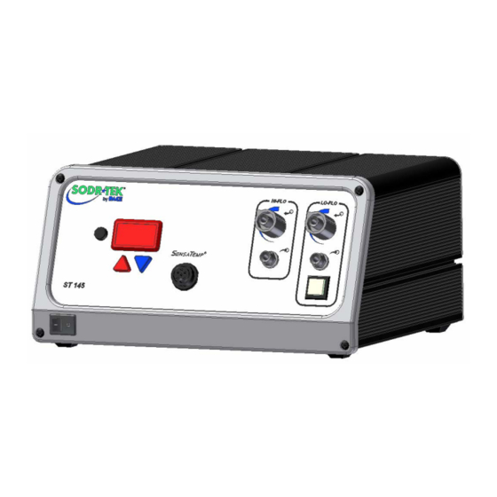
- Page 1 Operation and Maintenance Manual for the ® SODRTEK ST 145 Desoldering System P/N 5050-0535...
-
Page 2: Table Of Contents
LED Message Codes ..................17 Corrective Maintenance ....................18 Power Source ......................18 Handpieces......................18 Factory Settings ......................19 Definitions........................19 Packing List........................20 Spare Parts ........................20 Service ..........................20 Limited Warranty Form....................21 Contact Information.......................22 ©2004 PACE Inc., Annapolis Junction, Maryland Page 2 of 22 All Rights Reserved... -
Page 3: General Information
General Information Introduction ® Thank you for purchasing the PACE SODRTEK model ST 145 Analog Desoldering System. This manual will provide you with the information necessary to properly set up, operate and maintain the ST 145. The ST 145 system is available in either 115 VAC or 230 VAC versions, which incorporates a highly responsive SensaTemp (closed loop) control system providing up to 80 Watts of total power to a single output channel. -
Page 4: Parts Identification
LoFlo Vacuum Port Power Switch Scroll Down Key Power Receptacle Illuminated LoFlo Pump HiFlo Vacuum Port Switch Earth Ground Receptacle TEKLINK Receptacle Fuse AC Power Receptacle/Fuse Holder ©2004 PACE Inc., Annapolis Junction, Maryland Page 4 of 22 All Rights Reserved... -
Page 5: Safety
Always store the handpiece in its holder. Be sure to place the handpiece in its holder after use and allow for cooling before storing. 5. Always use PACE systems in a well ventilated area. A fume extraction system such as those available from PACE are highly recommended to help protect personnel from solder flux fumes. -
Page 6: System Set-Up
25/45 system through the VACUUM and PRESSURE ports of your ST 125/145. To link your ST 125/145 system to the ST 25/45 system, perform the following procedure. ©2004 PACE Inc., Annapolis Junction, Maryland Page 6 of 22 All Rights Reserved... -
Page 7: System Power Up
CAUTION: To insure operator and ESD/EOS safety, the AC power supply receptacle must be checked for proper grounding before initial operation. Set-Up Mode PACE recommends that you not read the “Set-Up Mode” section until after you feel comfortable with system operation. Please read the following “Operation" section thoroughly before changing the system settings. -
Page 8: Entering Set-Up Mode
Press and release the Program ( ) Key to keep the stored High Temperature Limit. b) Press and release the Scroll Up (s) Key to increase the stored High ©2004 PACE Inc., Annapolis Junction, Maryland Page 8 of 22 All Rights Reserved... -
Page 9: Offset Constant
Press and release the Scroll Down Key to decrease or disable the stored Temperature Setback time. Press and release the Program ( ) Key to proceed to the next step. ©2004 PACE Inc., Annapolis Junction, Maryland Page 9 of 22 All Rights Reserved... -
Page 10: Auto Off
The cap is used for shipping purposes only. 3. Press and hold the Program ( ) and Scroll Up keys together. 4. Place Power Switch in “ON” (I) position. ©2004 PACE Inc., Annapolis Junction, Maryland Page 10 of 22 All Rights Reserved... -
Page 11: Quick Start Procedure
5 seconds, the system will revert to normal operation. Allow time for the system to change back. 4. Press the Scroll Up Key. The Set Temperature is now displayed; immediately perform step 5. 5. Adjust the Set Temperature in the following manner: ©2004 PACE Inc., Annapolis Junction, Maryland Page 11 of 22 All Rights Reserved... - Page 12 NOTE: Read the “Operation” and “Set-Up Mode” sections of this manual to utilize the full capabilities of the system. This is especially important when using large soldering tips or other SensaTemp handpieces. ©2004 PACE Inc., Annapolis Junction, Maryland Page 12 of 22 All Rights Reserved...
-
Page 13: Operation
12. If you have a Sodr-X-Tractor or other PACE air handpiece connected to your system, press and hold the handpiece Vacuum Switch. You will hear a noise as the motor pump starts up and continues to run. Release the Vacuum Switch. -
Page 14: Led Display Temperature Adjust Mode
5. "no" will be displayed if the entered password does not match the stored Password. Vacuum Pump Operation The PACE ST 145 contains two different vacuum pumps. 1. HiFlo Pump a) To activate, depress the handpiece activation button. b) Optional Foot Pedal can be used to actuate the HiFlo pump via the rear TEKLINK socket. - Page 15 Insert the end of the quick connect hose mount fitting (on VisiFilter FLOW OUT side) into the power source Vacuum Port. 3. When using air pressure, and/or utilizing multiple air handpieces, PACE recommends the use of the following set up procedure which utilizes additional quick connect hose mount fittings. An assortment of quick connect air fittings are supplied with each additional air handpiece.
-
Page 16: Temperature Setback Mode
LED Display as the Operating Tip Temperature stabilizes at the Set Tip Temperature. For optimum performance, do not attempt to use the attached handpiece until the Set Tip Temperature is achieved. ©2004 PACE Inc., Annapolis Junction, Maryland Page 16 of 22 All Rights Reserved... -
Page 17: Auto Off Safety System Mode
The LED Display is flashing. The handpiece heater assembly may be defective. Refer to the respective handpiece manual. Power source malfunction. Contact the PACE Service Department for assistance. The LED Display is flashing. ©2004 PACE Inc., Annapolis Junction, Maryland... -
Page 18: Corrective Maintenance
Replace the fuse (located in the AC Receptacle Fuse Holder) with one of the same rated value. Power Source Malfunction Contact the PACE Service Department for assistance. Insufficient vacuum or Handpiece air hose has a kink Check handpiece hose. Replace air hose if air pressure. -
Page 19: Factory Settings
(impeded) for two seconds when a load is applied to the tip. Two seconds after the load is removed, the displayed temperature will begin rising to set temperature. Particularly useful in a ©2004 PACE Inc., Annapolis Junction, Maryland Page 19 of 22... -
Page 20: Packing List
Fuse, 0.63 Amp, 250 V, Time Lag (ST 145E) 1159-0252-P5 TEKLINK Cable 1332-0252-P1 TEKLINK Remote Box 3008-0218-P1 Tip & Temperature Selection Chart 5050-0251 Service Please contact PACE or your local distributor for service and repair. ©2004 PACE Inc., Annapolis Junction, Maryland Page 20 of 22 All Rights Reserved... -
Page 21: Limited Warranty Form
Warranty service may be obtained by contacting the appropriate PACE Company or local Authorized PACE distributor as set forth below to determine if return of any item is required, or if repairs can be made by the user in the field. Any warranty or other claim with respect to the products must be made with sufficient evidence of purchase and date of receipt, otherwise user’s rights under this warranty shall be... -
Page 22: Contact Information
PACE Incorporated retains the right to make changes to specifications contained herein at any time, without notice. Contact your local authorized PACE Distributor or PACE Incorporated to obtain the latest specifications. The following are trademarks and/or service marks of PACE, Incorporated, MD, USA: ™...
Need help?
Do you have a question about the Sodrtek ST 145 and is the answer not in the manual?
Questions and answers