Table of Contents
Advertisement
Quick Links
Advertisement
Table of Contents

Related Manuals for Pace SX-70


Summary of Contents for Pace SX-70
- Page 1 SX-70 SX-70 Sodr-X-Tractor Handpiece Operation & Maintenance Instructions...
- Page 2 Contact your local authorized PACE Distributor or PACE Incorporated to obtain the latest specifications. The following are registered trademarks and/or servicemarks of PACE Incorporated, Laurel Maryland U.S.A. and may only be used to identify genuine PACE products or services: Arm-Evac, Cir-Kit, ConducTweez, CRAFT, Flo-D-Sodr, Heat Wave,...
- Page 3 SX-70 SX-70 Sodr-X-Tractor Handpiece Part Number 6010-0100 Manual Number 5050-0334 Rev. E...
- Page 4 Its slim-line, pencil grip design and finger actuated vacuum switch facilitates ease of use and manipulation in tight places. The SX-70 is a member of the PACE SensaTemp family of advanced handpieces. CAUTION Always return heated handpieces to the appropriate Tip & Tool Stand when not in use.
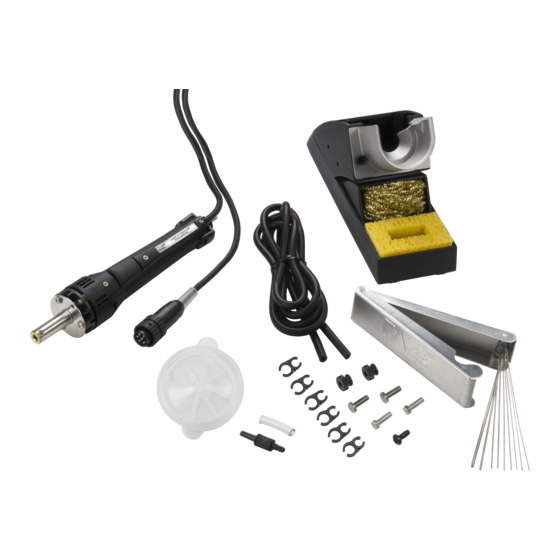
- Page 5 SX-70 Tip & Tool Stand Setup If you have purchased a SX-70 handpiece with a Tip & Tool Stand, set up the Tip & Tool Stand in the following manner. 1. Place 4 Rubber Feet on the bottom corners of the enclosed Tip & Tool Stand.
-
Page 6: Handpiece Setup
Handpiece Setup NOTE If using your SX-70 handpiece for the first time or if you have just replaced the heater, we recommend that you follow the “SX-70 Heater Burn-in” procedure (Red tag on handpiece) to increase the life expectancy of the heater. - Page 7 FLOW OUT side) into the power source Vacuum Port. 3. When using air pressure, and/or utilizing multiple air handpieces, PACE recommends the use of the following set up procedure which utilizes additional quick connect hose mount fittings. An assortment of quick connect air fittings are supplied with each additional air handpiece.
-
Page 8: Tip Selection
When removing TQFPs or TSOPs, the Pik-Tip should be sized so that the tip blades make proper contact with all the lead/land connections simultaneously. Tip Installation For maximum productivity and proper fit, install tips into your SX-70 Sodr-X-Tractor when the heater is hot. CAUTION Hold the handpiece with the heater pointed at an angle up to prevent injury to personnel. -
Page 9: Temperature Setting
SX-70 Temperature Setting To save tip life and reduce the possibility of damage to the PCB, PACE recommends using the lowest possible tip temperature that will provide rapid yet controllable melt of the entire solder joint. Begin with an operating temperature of 316°C (600°F) and adjust as necessary. - Page 10 SX-70 Thru-Hole Solder Extraction 1. Ensure that the air hose is connected to a VisiFilter and the Vacuum Port on the power source. Select an operating temperature that will cause complete solder melt in 2-5 seconds (somewhat longer on heavy multilayer boards).
-
Page 11: Tip Cleaning
7. Retin tip using large gauge flux cored solder and return SX-70 to its Tip & Tool Stand. 8. After all leads are desoldered, the component is easily removed. If any solder should remain in the plated thru-hole after extraction, resolder the connection and perform this procedure again. - Page 12 SX-70 Cleaning Solder Collection Chamber As the Sodr-X-Tractor is used, solder and flux buildup will begin to impede the air flow and decrease system performance. Regular cleaning of the chamber will keep the Sodr-X-Tractor operating at peak performance. When cleaning the chamber, perform the following procedure using the illustration as a reference.
- Page 13 SX-70 4. Clean and inspect the solder collection chamber in the following manner: a) Glass Chambers - Push the S Baffle (item ) and Filter (item  from the chamber. A bristle brush may be used for this purpose.
-
Page 14: Corrective Maintenance
SX-70 Corrective Maintenance Your SX-70 requires no special maintenance other than being kept clean. The heater bore and the heater assembly set screw which secures the tip must be kept free of oxidation and debris in order to maintain the proper tip-to-ground resistance. -
Page 15: Spare Parts
SX-70 Spare Parts Description Part Number Handle Assembly Kit 6993-0140 Heater Assembly 6010-0080-P1 Heater Set Screw 1348-0547-P10 Front (heater) Seal 1213-0033 Cord/Switch Assembly 4010-0098 Rear Seal Assembly 4010-0101 Glass Chamber 1265-0009-P1 Tubing, Silicone, Translucent, 54 Inches Long 1342-0001-13 Holder, Tube To Wire (pkg. of 6) 1321-0085-01 "S"...
Need help?
Do you have a question about the SX-70 and is the answer not in the manual?
Questions and answers