Advertisement
Quick Links
Advertisement

Subscribe to Our Youtube Channel
Related Manuals for Amprobe ROBIN KMP7010


Summary of Contents for Amprobe ROBIN KMP7010
- Page 1 KMP7010 Ground Resistance Tester Users Manual...
- Page 3 KMP7010 Ground Resistance Tester Users Manual June 2011, Rev.1 ©2011 Amprobe Test Tools. All rights reserved. Printed in China...
- Page 4 Amprobe® Test Tools distributor for an exchange for the same or like product. Please check the “Where to Buy” section on www.amprobe. com for a list of distributors near you. Additionally, in the United States and Canada In-Warranty repair and replacement units can also be sent to a Amprobe®...
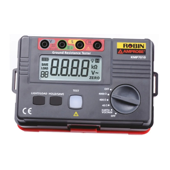
- Page 5 KMP7010 Ground Resistance Tester LCD Display Input terminals LIGHT/LOAD button Standard 3-Wires Test leads with alligator clip (Red, Yellow, Green) HOLD/SAVE button Auxiliary earth stakes TEST button 2 Wires test leads with alligator ON/OFF function clip (Red, Green)
-
Page 6: Table Of Contents
KMP7010 Ground Resistance Tester CONTENTS SYMBOLS .......................2 UNPACKING AND INSPECTION ................4 FEATURES .......................4 OPERATION ......................5 SPECIFICATION ......................9 MAINTENANCE AND REPAIR ................10 Battery Replacement ..................10... -
Page 7: Symbols
SYMBOLS � Battery Refer to the manual Caution! Risk of electric Double Insulated shock Complies with EU � Earth Ground directives Do not dispose of this product as unsorted municipal waste WARNING! � Do not operate this instrument in the presence of gasoline, natural gas, propane, or in other combustible atmospheres. - Page 8 DANGER! : identifies conditions and actions that most likely pose � hazard(s) or death. WARNING!: identifies conditions and actions that will pose hazard(s) or � death. CAUTION : identifies conditions and actions that will pose hazard(s) or � damage the Tester. DANGER! �...
-
Page 9: Unpacking And Inspection
ROBIN-AMPROBE Ground Testers are designed to measure resistance of the grounding systems to verify that the system has low enough resistance to provide protection for people, equipment and structures. -
Page 10: Operation
• Built-in memory to store 20 measurement • Low Battery Indication • Supplied with: Three Test Leads (Green, Yellow and Red) with alligator clip, Auxiliary ground stakes, two test leads with alligator clips • Safety CAT III 400V Range of application: This product is intended to be used to measure installation in process plants, industrial installations, and residential applications. - Page 11 Earth Resistance Measurement Display Range Accuracy 0.00 – 40.00Ω ±(2% Rdg +20 LSD) 0.0 – 400.0Ω ±(2% Rdg +3 LSD) 0 – 4000Ω ±(2% Rdg +3 LSD) Test Condition Relative Humidity: ≤75%RH Auxiliary Earth Resistance: 500e (Accuracy ±5%) Earth Voltage: ≤10Vac EN 61557-5 Measurement Range: 10Ω...
- Page 12 2. Earth Voltage Testing: Turn the rotary switch to select EARTH VOLTAGE. Connect the test leads to terminal V and E, and then connect to the testing points. LCD display will display earth voltage value. Voltage Measurement Range Accuracy 0 -400V AC, 50/60 Hz ±(1% Rdg + 6 LSD) Note:Do not press the TEST button when measuring the earth voltage.
- Page 13 Check the wiring connections, if soil is too dry, or if auxiliary earth stakes are within the specified measurement distance. When the earth resistance is greater than the selected measuring range, LCD display will show “OL”(overload). 4. Auto Power Off: The tester will turn itself off after 10 minutes when in idle.
-
Page 14: Specification
Simple measurement(use simple 2-Wires test leads for measurement): This method will be used when the auxiliary earth stakes cannot be used. Use the exposed earth resistance object from the ground as earth, like metal water bath, water pipe, ground wire, building earth, also can use 2-wires test leads method (E and S&H terminals).Connection diagram is as below: Supply Transformer Primary... -
Page 15: Maintenance And Repair
MAINTENANCE AND REPAIR If there appears to be a malfunction during the operation of the meter, the following steps should be performed in order to isolate the cause of the problem. 1. Check the battery. Replace the battery immediately when the symbol “...
Need help?
Do you have a question about the ROBIN KMP7010 and is the answer not in the manual?
Questions and answers