Table of Contents
Advertisement
Quick Links
Advertisement
Table of Contents

Related Manuals for Minebea Intec Mini FLEXLOCK


Summary of Contents for Minebea Intec Mini FLEXLOCK
- Page 1 Installation manual Mini FLEXLOCK mounting kits PR 6043/30N+S, PR 6043/40N+S Translation of the original installation manual 9499 053 28800 Edition 1.5.0 01/29/2020 Minebea Intec GmbH, Meiendorfer Str. 205 A, 22145 Hamburg, Germany Phone: +49.40.67960.303 Fax: +49.40.67960.383...
- Page 2 Any information in this document is subject to change without notice and does not represent a commitment on the part of Minebea Intec unless legally prescribed. This product should only be operated/installed by trained and qualified personnel. In correspondence concerning this product, the type, name, and release number/serial number as well as all license numbers relating to the product have to be cited.
-
Page 3: Table Of Contents
Mini FLEXLOCK mounting kits PR 6043/30N+S, PR 6043/40N+S Table of contents Table of contents Introduction............................2 Read the manual................................. 2 This is what operating instructions look like ......................2 This is what lists look like............................2 This is what menu items and softkeys look like..................... 2 This is what the safety instructions look like...................... -
Page 4: Introduction
Mini FLEXLOCK mounting kits PR 6043/30N+S, PR 6043/40N+S 1 Introduction Introduction Read the manual Please read this manual carefully and completely before using the product. This manual is part of the product. Keep it in a safe and easily accessible location. -
Page 5: Hotline
1 Introduction Mini FLEXLOCK mounting kits PR 6043/30N+S, PR 6043/40N+S NOTICE Warning of damage to property and/or the environment. NOTICE indicates that damage to property and/or the environment may occur if appropriate safety measures are not observed. Take the corresponding safety precautions. -
Page 6: Safety Instructions
If there are grounds for rejection of the goods, a claim must be filed with the carrier immediately. The Minebea Intec sales or service organization must also be notified. Before operational startup NOTICE Perform visual inspection. -
Page 7: Recommendations For Installation
3 Recommendations for installation Mini FLEXLOCK mounting kits PR 6043/30N+S, PR 6043/40N+S Recommendations for installation Load cell and constrainer arrangement Examples: Do not constrain this position. Constrainer Load application Possible direction of movement To ensure the required free moving space of the weighing facility, a maximum of 3 mounting kits with constrainer may be used to constrain a weighing object. -
Page 8: Mounting Aid
Mini FLEXLOCK mounting kits PR 6043/30N+S, PR 6043/40N+S 3 Recommendations for installation Round containers are the exception (image ① and ②). In this case, any number of constrainers can be installed, provided that they are tangentially aligned. Special mounting kits are available for weighing points without constrainers. - Page 9 3 Recommendations for installation Mini FLEXLOCK mounting kits PR 6043/30N+S, PR 6043/40N+S For this purpose, the simplest version requires the following components: 1× threaded bar (1) 3× nut (2) 1× washer (3) Assembly: Mount the threaded bar (1) so that it has sufficient free moving space in the drill hole.
-
Page 10: Specifications
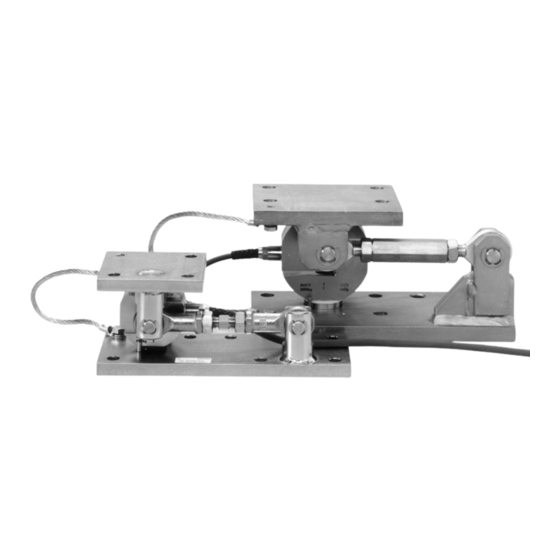
Mini FLEXLOCK mounting kits PR 6043/30N+S, PR 6043/40N+S 4 Specifications 4 Specifications Equipment supplied Example: Mounting kit PR 6043/30N+S Description Auxiliary mounting plate Screw (2×) and spring washer (2×) for the equipotential bonding cable (supplied with the load cell) Upper plate Constrainer with joint head (2×), screwed joint, nut (2×), bolts (2×), and locking... -
Page 11: Dimensions
4 Specifications Mini FLEXLOCK mounting kits PR 6043/30N+S, PR 6043/40N+S Dimensions PR 6043/30N+S * Right-hand thread, ** left-hand thread all dimensions in mm Minebea Intec EN-9... - Page 12 Mini FLEXLOCK mounting kits PR 6043/30N+S, PR 6043/40N+S 4 Specifications PR 6043/40N+S * Right-hand thread, ** left-hand thread all dimensions in mm EN-10 Minebea Intec...
-
Page 13: Technical Data
4 Specifications Mini FLEXLOCK mounting kits PR 6043/30N+S, PR 6043/40N+S Technical data PR 6043/30N+S PR 6043/30N PR 6043/30S Max. capacity of load cell 100 kg…2 t 100 kg…2 t Permissible horizontal force max. 6 kN max. 6 kN Horizontal destructive force >20 kN... -
Page 14: Installation
Mini FLEXLOCK mounting kits PR 6043/30N+S, PR 6043/40N+S 5 Installation Installation Prior to mounting 5.1.1 Preparing the foundation/substructure The foundation for the mounting kit must be horizontal (use spirit level), flat, and rigid for the intended loads. The load distribution on the available load cells must be as even as possible to prevent overload of the individual load cells. -
Page 15: Tightening Torques
5 Installation Mini FLEXLOCK mounting kits PR 6043/30N+S, PR 6043/40N+S Tightening torques The corresponding tightening torques are given in the following table. Mounting kit Mounting parts Thread Washer Tightening torque PR 6043/30N Upper plate M8-8.8 85 Nm Lower plate M8-8.8... -
Page 16: Installing The Mounting Kit And Inserting The Load Cell
Mini FLEXLOCK mounting kits PR 6043/30N+S, PR 6043/40N+S 5 Installation During any additional electrical welding work near the load cell: Disconnect the load cell cables. Bypass the load cell using the flexible copper strap. Make sure that the grounding clamp of the welding set is fitted as closely as possible to the welding joint. - Page 17 5 Installation Mini FLEXLOCK mounting kits PR 6043/30N+S, PR 6043/40N+S 6. Connect an equipotential bonding conductor (1) (not included) between the upper plate (3) and the lower plate (6). 7. Once all welding near the load cell and mounting work on the weighing object is complete, clean the recess for the load disc (10) in the upper plate (3) and the recess for the load plate (9) in the lower plate (6).
-
Page 18: Check Mounting
Mini FLEXLOCK mounting kits PR 6043/30N+S, PR 6043/40N+S 5 Installation Check mounting When all mounting kits have been installed, check them for proper mounting. In particular, force shunts should be avoided. Example: PR 6043/30N+S It is essential to check: whether the auxiliary mounting plate has been removed. -
Page 19: Cleaning
6 Cleaning Mini FLEXLOCK mounting kits PR 6043/30N+S, PR 6043/40N+S Cleaning The mounting kit is easy to clean. It can be spray-washed with water. For this purpose, spray the water jet from top to bottom and around the mounting kit. -
Page 20: Disposal
Mini FLEXLOCK mounting kits PR 6043/30N+S, PR 6043/40N+S 7 Disposal Disposal If the packaging is no longer required, please take it to your local waste disposal facility and/or a reputable disposal company or collection point. The packaging largely consists of environmentally friendly materials which can be used as secondary raw materials. -
Page 21: Spare Parts And Accessories
8 Spare parts and accessories Mini FLEXLOCK mounting kits PR 6043/30N+S, PR 6043/40N+S Spare parts and accessories Replacement parts Description Max. capacity Order no. Flexible copper thread, 250 mm long 5312 321 28056 Load disc kit (incl. O-ring) 100 kg…2 t 5312 693 98132 Load disc kit (incl. - Page 22 Published by Minebea Intec GmbH | Meiendorfer Strasse 205 A | 22145 Hamburg, Germany Phone: +49.40.67960.303 | Email: info@minebea-intec.com www.minebea-intec.com...
Need help?
Do you have a question about the Mini FLEXLOCK and is the answer not in the manual?
Questions and answers