Advertisement
Quick Links
Care Instructions:
PLACE THESE INSTRUCTIONS IN VEHICLE'S GLOVE BOX AFTER INSTALLATION IS COMPLETE.
LIST OF PARTS - 3PC TONNEAU COVER
Item
Component Name
1
Tonneau Cover
2
Left Hand Corner Piece
3
Right Hand Corner Piece
4
Drill Template
5
Hinge Base Plates
6
Hinge Pins
7
Hinge Pin Locking Tabs
8
Hex Head Self-tapping Screws
9
Countersunk Self-tapping Screws
10
Rubber Extrusion (1xLong, 2xShort)
11
Gas Strut Brackets
12
Ball Stud Screws
13
Lock Striker Brackets
14
Jacking Brackets
M8 Hex Head Bolts
15
16
M8 Hex Nuts
17
12gx1½" Self-tapping Screws
18
Plastic Spacers
RECOMMENDED TOOL LIST
Drill with Ø5mm, Ø10mm & 3/16" Drill Bits
Masking Tape
Tape Measure
Allen Key Screwdriver bits to suit M8
page 1 of 28
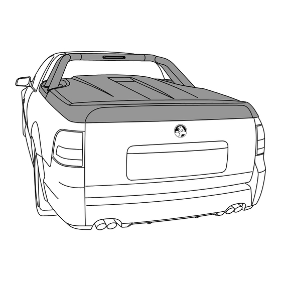
3PC TONNEAU COVER WITH
SPORTS BAR & REMOTE LOCKING
INSTALLATION INSTRUCTIONS
Holden VE Ute 2007
Part Number: EGR-3PVE-COLOUR
Clean Tonneau Cover & Sports Bar with
a mild detergent and water solution.
Non-Acetic Silicon & Caulking Gun
13mm Spanner
Torx Head Screwdriver & Bits
Wrench with 10mm Socket
Qty
Item
Component Name
1
19
M6x30mm Screws
1
20
M6 Flat Washers
1
21
M6 Spring Washers
1
22
Pop Rivets
2
23
Gas Struts
2
24
Clear Protection Pads
2
25
Flat Washers (14mm x 5.5mm)
8
26
Nut Inserts (4 Spare)
2
27
Hex Head Bolt
3
28
Wizlock Nut
2
29
20mm Allen Screws
2
30
Fibre Washers
2
31
Rubber Washers
2
32
Wiring Harness
Allen Key
2
33
4
34
Alcohol Wipe
4
35
Rust Inhibitor
4
36
Keys
Do not use abrasive
cleaners or solvents.
Non-permanent Marker
Rivet Gun
Phillips & Flat Head Screwdriver
Torque Wrench (¼" Drive)
TC0123b
Qty
4
4
4
4
2
6
4
12
1
1
8
8
12
1
1
1
1
2
21/05/08
Advertisement

Related Manuals for EGR EGR-3PVE-COLOUR


Summary of Contents for EGR EGR-3PVE-COLOUR
- Page 1 TC0123b 3PC TONNEAU COVER WITH SPORTS BAR & REMOTE LOCKING INSTALLATION INSTRUCTIONS Holden VE Ute 2007 Part Number: EGR-3PVE-COLOUR Clean Tonneau Cover & Sports Bar with Do not use abrasive Care Instructions: a mild detergent and water solution. cleaners or solvents.
- Page 2 TC0123b 3PC TONNEAU COVER WITH SPORTS BAR & REMOTE LOCKING 3PC TONNEAU COVER PARTS page 2 of 28 21/05/08...
- Page 3 TC0123b 3PC TONNEAU COVER WITH SPORTS BAR & REMOTE LOCKING LIST OF PARTS - SPORTS BAR Item Component Name Item Component Name Sports Bar Top Tube M4 Internal Tooth Washers Sports Bar Left Hand Leg Foot Gasket Left Hand Front Sports Bar Right Hand Leg Foot Gasket Left Hand Rear Rubber Sleeves...
-
Page 4: Maintenance
Disclaimer In the event that your EGR Tonneau Cover is found to be defective under the terms of this warranty, it is at the discretion of EGR to repair or replace the defective part. Transportation costs and labour are not associated with this warranty claim. - Page 5 TC0123b 3PC TONNEAU COVER WITH SPORTS BAR & REMOTE LOCKING Diagram #1 1. NOTE: Two people are required to complete installation. Thoroughly clean and dry the installation areas. See Dia #1. IMPORTANT: If vehicle is fitted with an LED brake light at the top of the rear window, proceed to Diagram #2.
- Page 6 TC0123b 3PC TONNEAU COVER WITH SPORTS BAR & REMOTE LOCKING DRILL TEMPLATE Ø5mm Ø10mm REMOVE DRILL TEMPLATE HINGE BASE 10mm PLATE MARK, CENTRE PUNCH, DRILL Ø5mm THEN Ø10mm HOLES & APPLY RUST INHIBITOR Diagram #4 4. Fit hinge base plates into cut-out in drill template as shown. Mark four (4) holes in front of hinge base plate. Remove hinge base plates.
- Page 7 TC0123b 3PC TONNEAU COVER WITH SPORTS BAR & REMOTE LOCKING HINGE BASE PLATE HINGE BASE HINGE PIN HINGE BASE PLATE LOCKING TAB PLATES TORQUE 8Nm NON-ACETIC FIBRE WASHERS SILICON & DRILL TEMPLATE CAULKING GUN ALLEN SCREWS Diagram #6 6. Apply non-acetic silicon to the underside of the hinge base plates and position on the vehicle, aligning the four (4) holes on the hinge with those on the header rail as well as inside the cut-out of the drill template.
- Page 8 TC0123b 3PC TONNEAU COVER WITH SPORTS BAR & REMOTE LOCKING RUBBER RIGHT HAND SLEEVE RUBBER TUBE FRONT SLEEVE RIGHT HAND RUBBER SLEEVE TUBE TOP TUBE RUBBER LEFT HAND SLEEVE WIRING Diagram #9 9. Slide the rubber sleeves over the ends of the Sports Bar left hand leg and right hand leg and then slide the Sports Bar top tube in as shown.
- Page 9 TC0123b 3PC TONNEAU COVER WITH SPORTS BAR & REMOTE LOCKING RIGHT HAND SHOWN SPORTS BAR RIGHT HAND LEG FOOT GASKET RIGHT HAND REAR LED WIRING FOOT GASKET RIGHT HAND FRONT Diagram #12 12. Attach the foot gaskets to their correct Sports Bar foot as shown, ensuring the holes in the Sports Bar feet remain accessible. Repeat process for the other side of the vehicle.
- Page 10 TC0123b 3PC TONNEAU COVER WITH SPORTS BAR & REMOTE LOCKING TAILGATE SEAL BEDLINER BEDLINER STOP LIGHT WIRING PLUG Diagram #15 15. Lift and pull the bedliner as shown to gain access to the wiring located in the side panel of the vehicle. Disconnect the stop light wiring plug located behind the bedliner, by pushing down on the tag on the connector using you finger or a flat blade screwdriver.
- Page 11 TC0123b 3PC TONNEAU COVER WITH SPORTS BAR & REMOTE LOCKING CONNECT 2-WAY CONNECTORS (WIRING HARNESS) 2-WAY CONNECTORS 2-WAY 2-WAY (VEHICLE) CONNECTORS CONNECTORS (VEHICLE) (VEHICLE) UNCLIP FROM MOUNT DISCONNECT CONNECT Diagram #18 18. Find the white 2-way connectors on the vehicle (directly behind the wheel arch) and unclip them from the vehicle as shown. Disconnect the white 2-way connectors.
- Page 12 TC0123b 3PC TONNEAU COVER WITH SPORTS BAR & REMOTE LOCKING WIRING HARNESS 4-WAY GREY (BEHIND BEDLINER) 4-WAY GREY CONNECTOR CONNECTOR (WIRING HARNESS) 200mm WIRING HARNESS Diagram #21 21. Run the grey 4-way connector from the wiring harness all the way to the front of the tub behind the bedliner as shown. At the front of the tub, pull the grey 4-way connector 200mm out from behind the bedliner as shown.
- Page 13 TC0123b 3PC TONNEAU COVER WITH SPORTS BAR & REMOTE LOCKING RIGHT HAND SHOWN LEFT HAND CORNER PIECE M6x30mm SCREWS SPORTS M6 SPRING WASHER RIGHT HAND CORNER PIECE RIGHT HAND M6 FLAT CORNER PIECE WASHER LED WIRING SPORTS LOOM Diagram #24 24.
- Page 14 TC0123b 3PC TONNEAU COVER WITH SPORTS BAR & REMOTE LOCKING TRIAL-FIT RUBBER EXTRUSION MARK LINE ALONG EXTRUSION CLEAN WITH ALCOHOL WIPES RUBBER REMOVE PROTECTIVE LINING EXTRUSION ATTACH RUBBER EXTRUSION FIRST MARKED LINE DRAWN LINE Diagram #27 27. Trial-fit the rubber extrusion to the header rail, aligning it with the back of the hinge base plates as shown and to the first previously marked line.
- Page 15 TC0123b 3PC TONNEAU COVER WITH SPORTS BAR & REMOTE LOCKING RIGHT HAND ONLY SPORTS BAR RIGHT HAND LEG ENSURE TIGHT BULB SEAL CLAMPING PLATE LED WIRING LOOM BEDLINER TIGHTEN M6 SCREWS Diagram #30 30. Fit the Sports Bar to the vehicle as shown. Note the corner piece positions over the top of the previously installed rubber extrusion. Ensure the corner pieces are tightly fitted around the vehicle sail-plane panels, then tighten the M6 screws as shown.
- Page 16 TC0123b 3PC TONNEAU COVER WITH SPORTS BAR & REMOTE LOCKING RIGHT HAND SHOWN RIGHT HAND SHOWN CLAMPING CLAMPING RIGHT HAND RIGHT HAND PLATE PLATE FRONT LEG REAR LEG WASHER WASHER PLATE PLATE 12Gx1½” SELF 12Gx1½” SELF M6 SPRING M6 SPRING TAPPING TAPPING WASHER...
- Page 17 TC0123b 3PC TONNEAU COVER WITH SPORTS BAR & REMOTE LOCKING RIGHT HAND SHOWN UNDERSIDE OF CORNER JACKING PIECE BRACKET TORQUE HEX HEAD SELF- TAPPING SCREWS Diagram #36 36. Attach the jacking bracket to the side rail using the hex head self-tapping screws as shown. Tighten to torque 3Nm. Repeat the process for the other side of the vehicle.
- Page 18 TC0123b 3PC TONNEAU COVER WITH SPORTS BAR & REMOTE LOCKING RIGHT HAND SHOWN Ø5mm GAS STRUT BRACKET 10mm CENTRE PUNCH, DRILL Ø5mm HOLES & ALIGN BRACKET APPLY RUST INHIBITOR WITH MARK Diagram #39 39. Fit the gas strut bracket into the side rail, aligning it with the previously drawn mark as shown. Centre punch and drill Ø5mm holes at the two (2) outer hole positions on the gas strut bracket.
- Page 19 TC0123b 3PC TONNEAU COVER WITH SPORTS BAR & REMOTE LOCKING RIGHT HAND SHOWN RIGHT HAND SHOWN SIDE RAIL PANEL TORX HEAD SCREWS 3RD SCREW Diagram #42 42. Using a torx head screwdriver, retrieve the torx head screws from inside the side rail panel as shown. If you drop one of the torx head screws inside the panel, simply remove the 3rd screw and slide the panel upwards to retrieve it.
- Page 20 TC0123b 3PC TONNEAU COVER WITH SPORTS BAR & REMOTE LOCKING ENSURE CLEARANCE TO TUB LOOSEN HINGE SCREWS TO ADJUST TONNEAU RE-TORQUE 5Nm POSITION IF NECESSARY NEXT STEP Diagram #45 45. Check Tonneau Cover is central to vehicle and the sides of Tonneau Cover do not contact the vehicle bed rail. Adjust position if necessary by loosening the top hinge screws and re-positioning Tonneau Cover to fit centrally on vehicle.
- Page 21 TC0123b 3PC TONNEAU COVER WITH SPORTS BAR & REMOTE LOCKING IMPORTANT: Ensure vehicles’s tailgate remains open whilst adjusting Tonneau Cover locking mechanism. INSPECT LATCH ADJUST STRIKER BRACKET ENGAGEMENT LOCK INCORRECT STRIKER BRACKET IF THE HORIZONTAL POSITION OF THE LATCH LOOSEN CORRECT MECHANISM REQUIRES ADJUST...
- Page 22 TC0123b 3PC TONNEAU COVER WITH SPORTS BAR & REMOTE LOCKING REMOVE ACTUATOR FROM RELEASE PLASTIC UNCLIP RODS FROM ADJUST LATCH INSPECTION AREA RETAINER CLIPS PLASTIC RETAINER MECHANISM CLIPS ADJUST SCREWS PLASTIC RETAINER ACTUATOR RODS CLIPS Diagram #50 50. Remove the actuator from the inspection area and let it hang out of the hole as shown. Release plastic retainer clips and unclip rods as shown.
- Page 23 TC0123b 3PC TONNEAU COVER WITH SPORTS BAR & REMOTE LOCKING RIGHT HAND SHOWN RIGHT HAND SHOWN Ø5mm LOCK STRIKER LOCK STRIKER BRACKET BRACKET 10mm CENTRE PUNCH, DRILL Ø5mm HOLES POP RIVETS & APPLY RUST INHIBITOR Diagram #53 53. Now that the lock striker bracket has been positioned correctly, centre punch and drill Ø5mm holes through the bracket and into the side rail as shown.
- Page 24 TC0123b 3PC TONNEAU COVER WITH SPORTS BAR & REMOTE LOCKING STRUT GENTLY OPEN CYLINDER CLOSE TONNEAU COVER TONNEAU ENSURE CONTACT LOOSEN TIGHTEN HAS BEEN MADE SCREW SCREW Diagram #56 56. Loosen the screw found on the terminal housing on the driver’s side gas strut, until it can move up and down the strut freely. With the tailgate open, gently close the Tonneau Cover.
- Page 25 TC0123b 3PC TONNEAU COVER WITH SPORTS BAR & REMOTE LOCKING TONNEAU COVER INTERIOR LIGHT Diagram #59 59. Open and close the Tonneau Cover with the tailgate open to check whether or not the Tonneau Cover interior light is functioning correctly. Ensure that the light turns on when the Tonneau is open and turns off when the Tonneau is closed. If the light DOES NOT work, check adjustment of the gas strut switch (refer to Diagram #56).
- Page 26 TC0123b 3PC TONNEAU COVER WITH SPORTS BAR & REMOTE LOCKING REMOVAL OF TONNEAU COVER UNDERSIDE OF DRIVER’S SIDE ONLY TONNEAU COVER GAS STRUT WIRING HARNESS STRUT 4-WAY STRUT GAS STRUT CONNECTORS BALL STRUT SCREW BOTTOM Diagram #1 1. Open Tonneau Cover, pull the 4-way connectors out from behind the bedliner and disconnect them. Disconnect the wiring harness from the terminals on the driver’s side gas strut.
- Page 27 TC0123b 3PC TONNEAU COVER WITH SPORTS BAR & REMOTE LOCKING REPLACEMENT OF TONNEAU COVER RIGHT HAND SHOWN RIGHT HAND SHOWN HINGE HINGE “CLICK” Diagram #1 1. Fit Tonneau Cover and secure hinges with hinge pins as shown. See Dia #1. LARGE DRIVER’S SIDE ONLY UNDERSIDE OF...
- Page 28 TC0123b 3PC TONNEAU COVER WITH SPORTS BAR & REMOTE LOCKING HOLDEN VE UTE 2007 3PC HARD TONNEAU COVER KEY IDENTIFICATION CODE Please write your key identification code in the boxes above and retain. Replacement keys can be purchased from your local Holden dealer. page 28 of 28 21/05/08...
Need help?
Do you have a question about the EGR-3PVE-COLOUR and is the answer not in the manual?
Questions and answers