
Subscribe to Our Youtube Channel
Related Manuals for Motomaster ELIMINATOR 11-1586-4


Summary of Contents for Motomaster ELIMINATOR 11-1586-4
- Page 1 011-1586-4 Intelligent Battery Charger with Engine Start ’...
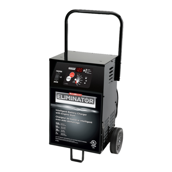
- Page 3 BATTERY CHARGER Owner’s Manual MODEL 11-1586-4 Intelligent Battery Charger with Engine Start • 150 A Engine Start • 55 A Express Charge • 20 A Fast Charge • 2 A Trickle Charge Suitable for all 12 V lead-acid batteries, including deep cycle and AGM Fully automatic •...
-
Page 4: Table Of Contents
TABLE OF CONTENTS INTRODUCTION ..................SAFETY INFORMATION Important Safety Instructions . -
Page 5: Introduction
• Use only recommended attachments. Use of attachments not recommended or sold by MotoMaster® may result in a risk of fire, electric shock or injury to persons, or damage to property. • To reduce the risk of damage to the electric plug or cord, pull by the plug rather than the cord when disconnecting the charger. -
Page 6: Personal Safety Instructions
SAFETY INFORMATION (cont’d) Personal Safety Instructions W A R N I N G RISK OF EXPLOSIVE GASES • NEVER smoke or allow a spark or flame in the vicinity of a battery or engine. • Remove personal metal items such as rings, bracelets, necklaces and watches when working with a lead-acid battery. -
Page 7: Preparing To Charge
SAFETY INFORMATION (cont’d) • This battery charger is for use on a nominal 120 V circuit and has a 3-pronged grounded plug. The charger must be grounded to reduce the risk of electric shock. The plug must be plugged into an outlet that is properly installed and grounded in accordance with all local codes and ordinances. -
Page 8: Charger Location
SAFETY INFORMATION (cont’d) Charger Location W A R N I N G RISK OF EXPLOSION AND CONTACT WITH BATTERY ACID. • Locate the charger as far away from the battery as the DC cables permit. • NEVER place the charger directly above the battery being charged; gases from the battery will corrode and damage the charger. - Page 9 ASSEMBLY INSTRUCTIONS (cont’d) Attach the Foot – Remove the charger from Assemble the Wheels and Axle – Hold the the packing materials and place upside down axle upright on the floor or work surface. Then, on a flat surface. Attach the foot (1) and secure using a hammer, tap one of the axle caps onto it (2) with the four 1/4”...
-
Page 10: Understanding Controls & Features
UNDERSTANDING CONTROLS & FEATURES Controls Function Auto Digital Display Mode Display Switch Start Button Display Mode LEDs Connected (Red) Charging (Yellow) Charged (Green) Charge Rate Timer Time Control LEDs Button Function Switch Use this switch to select between the different charge rates and the engine start mode. • (O) Position: When the switch is in this position (middle), the charger is turned off. -
Page 11: Digital Display
UNDERSTANDING CONTROLS & FEATURES (cont’d) while allowing a battery time to obtain a satisfactory charge. To properly set the timer, you must know the size of the battery in ampere hours or reserve capacity in minutes and the state of charge. It is important that you determine the appropriate state of charge of your battery as specified. -
Page 12: Connecting Your Battery
CONNECTING YOUR BATTERY Battery in Vehicle (Negative Grounded) – – Before connecting and disconnecting the Connect the POSITIVE (RED) clip from the DC output clamps, remove the AC plug from battery charger to the POSITIVE (POS, P, +) the electrical outlet. ungrounded post of the battery. -
Page 13: Battery In Vehicle (Positive Grounded)
CONNECTING YOUR BATTERY (cont’d) Battery in Vehicle (Positive Grounded) – – Before connecting and disconnecting the Connect the NEGATIVE (NEG, BLACK) clip DC output clamps, remove the AC plug from from the battery charger to the NEGATIVE the electrical outlet. (NEG, N, –) ungrounded post of the battery. -
Page 14: Battery Removed From Vehicle
CONNECTING YOUR BATTERY (cont’d) Battery Removed from Vehicle – + + + Before connecting and disconnecting the Position yourself and the free end of cable DC output clamps, remove the AC plug from as far away from battery as possible, then the electrical outlet. -
Page 15: Charging Your Battery
CHARGING YOUR BATTERY Normal Operation 1. Ensure that all of the charger components are in place and in good working condition (for example, the plastic boots on the battery clips). 2. Connect the battery following the precautions listed in Safety Information. 3. -
Page 16: Timed Charging
CHARGING YOUR BATTERY (cont’d) Timed Charging Timed Charger Settings 1. Set the Function switch to the desired charge rate setting. 2. Press the Charge Rate button to select the desired charge rate. 3. Press the Timer Control button to select the charging time you need. Pressing the Timer Control button as many times as necessary allows you to cycle through the charging times or turn off the timer. -
Page 17: Calculating Charge Times
CHARGING YOUR BATTERY (cont’d) Calculating Charge Times Battery Percent and Charge Time In automatic mode this charger adjusts the charging time in order to charge the battery completely, efficiently and safely. The microprocessor automatically performs the necessary functions. This section includes guidelines that can be used to estimate charging times. -
Page 18: Other Leds & Features
OTHER LEDs AND FEATURES Battery Status LEDs Connected (red LED) – Indicates that the charger is properly connected to the battery. • If the charger does not detect a properly (Red) connected battery, the CONNECTED LED will not light. Charging will NOT begin if the CONNECTED LED is not on. -
Page 19: Voltage Tester
Therefore, we do not recommend charging a large battery on the maintenance setting. NOTE: The maintain mode technology utilized in MotoMaster Eliminator chargers allows you to safely charge and maintain a healthy battery for extended periods of time. However, problems with the battery, electrical problems in the vehicle, improper connections or other unanticipated conditions could cause excessive current draws. -
Page 20: Alternator Performance Tester
OTHER LEDs AND FEATURES (cont’d) Tester and Charger – When first turned on, the unit operates only as a tester, not as a charger. To continue to use it only as a tester, avoid pressing the AUTO button or the TIMER button. Selecting a time or pressing the AUTO button activates the battery charger and deactivates the tester. -
Page 21: Jump-Starting Your Vehicle
JUMP-STARTING YOUR VEHICLE Using the Engine Start Feature Your battery charger can be used to jump-start your car if the battery is low. Follow these instructions on how to use the ENGINE START feature. W A R N I N G Follow all safety instructions and precautions for charging your battery. -
Page 22: Engine Starting Notes
JUMP-STARTING YOUR VEHICLE (cont’d) Failed Engine Start 1–2 seconds 3 seconds wait 4 minutes (battery still charging) 3 seconds 5. If the engine fails to start, wait 4 minutes (battery is still being charged) before attempting to crank the engine again. 6. -
Page 23: Moving & Storage
JUMP-STARTING YOUR VEHICLE (cont’d) • Cool Down – After cranking, the charger enters a mandatory 4 minute (240 second) cool down state. During this period, no settings can be changed. The buttons are ignored. The digital display indicates the remaining cool down time in seconds. It starts at 240 and counts down to 0. During the cool down period, the battery is still being charged. -
Page 24: Troubleshooting/Failure Codes
TROUBLESHOOTING/FAILURE CODES Failure Codes FAILURE CODE DESCRIPTION CAUSE The battery voltage is still under Could be caused by trying to charge a 10 V (for a 12 V battery) or 5 V 6 V battery on the 12 V charger, or the (for a 6 V battery) after 2 hours battery could be bad;... - Page 25 TROUBLESHOOTING/FAILURE CODES (cont’d) PROBLEM POSSIBLE CAUSE REASON/SOLUTION Battery clips do not spark when The charger is equipped with No problem; this is a normal touched together. an auto-start feature. It will not condition. supply current to the battery clips until a battery is properly connected.
- Page 26 TROUBLESHOOTING/FAILURE CODES (cont’d) PROBLEM POSSIBLE CAUSE REASON/SOLUTION Short or no start cycle when Drawing more than the engine Crank time varies with the cranking engine. start rate. amount of current drawn. If cranking draws more than the engine start rate, crank time may be less than 3 seconds.
-
Page 27: Maintenance And Care
TROUBLESHOOTING/FAILURE CODES (cont’d) Before Returning for Repairs • When a charging problem arises, make certain that the battery is capable of accepting a normal charge. Double check all connections, the AC outlet for a full 120 V, the charger clips for correct polarity and the quality of the connections from the cables to the clips and from the clips to the battery system. -
Page 28: Limited Warranty
PRODUCT. THIS LIMITED WARRANTY IS NOT TRANSFERABLE OR ASSIGNABLE. MotoMaster Canada warrants this battery charger for 3 years from the date of purchase at retail against defective material or workmanship that may occur under normal use and care. If your unit is not free from defective material or workmanship, the Manufacturer’s obligation under this warranty... - Page 43 –...
- Page 44 – –...
- Page 45 – –...
Need help?
Do you have a question about the ELIMINATOR 11-1586-4 and is the answer not in the manual?
Questions and answers
Que faire si j’ai connecté les câbles inversé
If the Motomaster ELIMINATOR 11-1586-4 cables are connected incorrectly, disconnect the AC cord, then remove the clip from the vehicle chassis first, and finally remove the clip from the battery terminal. Check the polarity of the battery posts and ensure the positive (POS, P, +) clip is connected to the positive battery post and the negative (NEG, N, –) clip is connected to the negative post. Reconnect correctly before charging.
This answer is automatically generated