Table of Contents
Advertisement
Advertisement
Table of Contents

Related Manuals for Lippert Components LCI Level-Up


Summary of Contents for Lippert Components LCI Level-Up
- Page 1 LCI Level-Up Motorhome LEVELING (2013-PRESENT) ® OWNER'S MANUAL...
-
Page 2: Table Of Contents
The use of the LCI Level-Up® Motorhome Leveling System to support the coach for any reason other than which it is intended is prohibited by Lippert's Limited Warranty. The LCI Level-Up® Motorhome Leveling System is designed as a "Leveling"... -
Page 3: Safety
Lippert Components Inc. recommends that a trained professional be employed to change the tires on the coach. Any attempts to change tires or perform other services while coach is supported by the LCI Level‑Up®... -
Page 4: Prior To Operation
When parking the coach on extremely soft surfaces, utilize load distribution pads under each jack. Make sure hands and other body parts are clear of fluid leaks. Oil leaks in the LCI Level-Up Motorhome Leveling system may be under high pressure and can cause serious skin penetrating injuries. -
Page 5: Touchpad Diagram
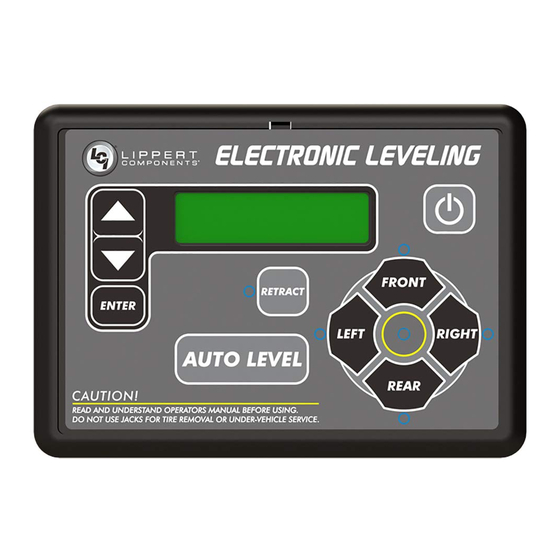
Touchpad Diagram Fig. 1 Gray Black NOTE: Units manufactured before January 2018 will utilize the black touchpad. Callout Description Up Arrow - Scrolls up through the menu on LCD. Down Arrow - Scrolls down through the menu on LCD. ENTER - Activates modes and procedures indicated on LCD. RETRACT - Places leveling system into retract mode. -
Page 6: Operation
Automatic Leveling Procedure Coach must be running for LCI Level-Up Motorhome Leveling system to operate. Press the ON/OFF (power) button (Fig. 1K) on the touchpad to turn the leveling system on. The leveling system is now operational and the electronic level lights will activate. -
Page 7: Jack Retract Procedures
NOTE: The right and left jacks are used to level the coach side-to-side. Pressing the LEFT button on the touchpad will extend both left jacks. Pressing the RIGHT button on the touchpad will extend both right jacks. Jacks always work in pairs; both front jacks, both right side (curbside) jacks, etc. Repeat steps 2-5 if needed. -
Page 8: Low Voltage Signal
Low Voltage Signal The vehicle requires 12.7V DC to operate in the AUTO mode. A. If the voltage is too low, the touchpad's LCD screen (Fig. 1E) will display "LOW VOLTAGE." B. If voltage drops below 12.7V DC, the leveling system will only operate in manual mode and continue to display "LOW VOLTAGE."... -
Page 9: User Alarm Mode
User Alarm Mode If the alarm system detects that the park brake has been disengaged while at least one jack is not fully retracted and the sensor value changes in any axis more than the predefined amount, the touchpad will signal this error to the user. - Page 10 Fig. 2 Clockwise for Manual Override Remove the plastic cap (Fig. 3A) from the end of the motor. Disconnect or shield power cables on the motor. Fig. 3 Page 10 Rev: 11.18.19 CCD-0001535...
- Page 11 Using a 1/2” socket and auxiliary drive device, e.g., cordless or electric power drill, insert 1/2” socket onto the coupler (Fig. 4A). Run drive device in reverse (counterclockwise) to retract jacks (Fig. 4)—forward (clockwise) to extend jacks. Fig. 4 Run Counterclockwise to Manually Retract Jacks.
-
Page 12: Troubleshooting
Troubleshooting For leveling system concerns, refer to the Leveling System Troubleshooting Chart. Error Mode Leveling System Troubleshooting Chart What Is Happening? Why? What Should Be Done? Coach ignition not in RUN position. Turn ignition to RUN position. System will not turn on Parking brake not set. -
Page 13: Error Mode
All normal functions will be disabled when the system is in Error Mode. Auto Level can only commence if running voltage is 12.7V DC or above. Auto Level operation will halt if running voltage drops to 9.5V DC. Manual Level operation can be performed at all running voltages above 9.5V DC. If an error occurs before or during operation, the error will be displayed in the LCD screen (Fig. -
Page 14: Maintenance
Maintenance For optimum performance, the system requires full battery current and voltage. The battery must be maintained at full capacity. Check the terminals and other connections at the battery, the controller, and the jacks for corrosion and loose or damaged connections. Remove dirt and road debris from jacks as needed. -
Page 15: Component Description
Component Description Aluminum Jacks Feature Figure 6 - 433458 Figure 7 - 433464 Figure 8 - 433472 Capacity 8000 lbs 14,000 lbs 20,000 lbs Stroke 15.00 inches 15.13 inches 16.00 inches Bore 2.00 inches 2.50 inches 3.00 inches 21.375 inches 21.50 inches 23.063 inches Rod Diameter... -
Page 16: Hydraulic Power Unit
Hydraulic Power Unit See figures 9 and 10 for hydraulic power unit feature identification and the following: • Fittings - High Pressure O-Ring Face - Size 4 • Hose - " I.D. 3000PSI - W.P. Rated NOTE: Fittings are labeled with port assignments found stamped into the manifold for easy identification. Fig. -
Page 17: 12-Pin Wire Harness
Fig. 10 Extend Quick Fittings Disconnect for Valve and Valve Coil Flush and Fill Fill Cup Quick Pressure Hydraulic Disconnect for Switch Manifold Return Flush and Fill Fittings 12-Pin Wire Harness See figure 11 for 12-Pin wire harness pin locations and definitions. Fig. -
Page 18: Wiring Diagram
Wiring Diagram Main Power Harness Touchpad Controller Touchpad Harness Interconnect Harness Rear Sensor Harness Power Unit Harness Directional Valve Pressure Switch Power Unit Manifold Valve Page 18 Rev: 11.18.19 CCD-0001535... -
Page 19: Hydraulic Plumbing Diagram
Hydraulic Plumbing Diagram Orange Left Front Right Front Jack Jack Black Black Orange Retract NOTE: Hose color/function— Power Unit • Orange/Retract • Black/Extend Retract Orange Orange Left Rear Right Jack Rear Jack Black Extend Black Page 19 Rev: 11.18.19 CCD-0001535... - Page 20 The contents of this manual are proprietary and copyright protected by Lippert Components, Inc. (LCI). LCI prohibits the copying or dissemination of portions of this manual unless prior written consent from an authorized LCI representative has been provided. Any unauthorized use shall void any applicable warranty. ...
Need help?
Do you have a question about the LCI Level-Up and is the answer not in the manual?
Questions and answers
I have a 2015 FLS337 cougar 5th wheel and I have no power to the touchpad for the leveling system. All the troubleshooting says is, Tripped breaker or turn the key on. Where is the breaker for that system?
@Michael M Silvers the touchpad is lit up and beeping, power is on.
control panel is on with error code and alarm is beeping. there is no way that i change the display or stop the beeping.