
Related Manuals for Lippert Components LCI Level-Up

Summary of Contents for Lippert Components LCI Level-Up
- Page 1 LCI Level-Up Motorhome Leveling (2013-Present) ® OWNER'S MANUAL Rev: 07.02.2018 Level-Up® Motorized Leveling LCD Owner's Manual...
-
Page 2: Table Of Contents
TABLE OF CONTENTS System Information Prior To Operation System Description Component Description Maintenance Fluid Recommendation Preventative Maintenance Procedures Aluminum Jacks Power Unit Components Touch Pad Controls Level Zero Point Calibration For Diesel Units With Air Bag Suspensions ONLY: Miscellaneous Low Voltage Signal Error Mode Excess Angle Error Mode... -
Page 3: System Information
When parking the coach on extremely soft surfaces, utilize load distribution pads under each jack. Be sure to keep hands and other body parts clear of fluid leaks. Oil leaks in the LCI Level-Up® Motorhome Leveling System may be under high pressure and can cause serious skin penetrating injuries. -
Page 4: Component Description
Maintenance Fluid Recommendation The LCI Level-Up Motorhome Leveling System is pre-filled, primed and ready to operate direct from the manufacturer. Automatic transmission fluid (ATF) with Dexron III or Mercon 5 or a blend of both is recommended by Lippert Components, Inc. Specific fluid information can be found on Page 15. -
Page 5: Aluminum Jacks
Aluminum Jacks Fig. 2 Fig. 3 Fig. 1 Fig. 1 - 433458 Fig. 2 - 236560 Fig. 3 - 258550 CAPACITY - 8,000 lb. CAPACITY - 14,000 lb. CAPACITY - 20,000 lb. STROKE - 15.00 in. STROKE - 15.13 in. STROKE - 16.00 in. -
Page 6: Power Unit Components
Power Unit Components Fig. 4 Motor Solenoid 12V DC Power 12V DC Motor Ground Quick Power Disconnect for Fig. 5 Flush and Fill Hydraulic Extend Manifold Fittings Valve and Valve Coil Pressure Switch Return Quick Fittings Disconnect for Flush and Fill Fill Cup Fittings - High Pressure O-Ring Face - Size 4 Hose - ¼"... -
Page 7: Touch Pad Controls
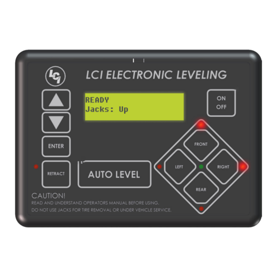
Touch Pad Controls Fig. 6 Callout Description Up Arrow - Scrolls up through the menu on LCD. Down Arrow - Scrolls down through the menu on LCD. Enter - Activates modes and procedures indicated on LCD. Retract - Places leveling system into retract mode. - Manual mode ONLY LCD Display - Displays procedures and results. -
Page 8: Level Zero Point Calibration
Level Zero Point Calibration Before auto leveling features are available, the Level Zero point MUST be set. This is the point to which the system will return when an auto leveling cycle is initiated. To set the zero point (controller module MUST be fully secured in production-intent location), first run a manual leveling sequence to get the vehicle to the desired level point. -
Page 9: Low Voltage Signal
Low Voltage Signal The vehicle requires 12.7V DC to operate in the AUTO mode. If the voltage is too low, the screen will display LOW VOLTAGE. If voltage drops below 12.7V DC, the system will only operate in the MANUAL MODE and continue to display LOW VOLTAGE. -
Page 10: Operation
Operation Selecting A Site When the coach is parked on an excessive slope the leveling requirements may exceed the jack lift stroke capability. If the coach is parked on an excessive slope, the coach should be moved to a more level surface before the leveling system is deployed. -
Page 11: Manual Leveling Procedure
Manual Leveling Procedure NOTE: When leveling your coach, the coach should be leveled from FRONT TO REAR first (step 2-4). When the coach is level from FRONT TO REAR, then level the coach from LEFT TO RIGHT (step 5). NOTE: Coach requires 12.7V DC to commence auto leveling function. If voltage at the power unit is not 12.7V DC, run the engine. -
Page 12: Manual Override - Jacks
Counterclockwise for normal operation Manual Override - Power System The Lippert LCI Level-Up Motorhome Leveling System can be run with auxiliary power devices like cordless or power drills. In the event of electrical or system failure, this manual method of extending and retracting the jacks can be used. -
Page 13: Automatic Safety Shutoff
The power unit will also operate to keep the jacks retracted in the event the leveling system loses pressure as the coach is being driven. “Jacks Down" Alarm The LCI Level-Up Motorhome Leveling System is designed to sound an alarm and illuminate the control panel in the event of two (2) possible scenarios: A “RETRACT” hose leaks. - Page 14 What Is Happening? Why? What Should Be Done? Coach ignition not in Turn ignition to RUN position. RUN position. System will not turn on Parking brake not set. Set parking brake. and On/Off indicator Controls have been light does not illuminate. on for more than four Turn ignition OFF and then back ON.
-
Page 15: Wiring Diagram
Wiring Diagram Main Power Harness Touch Pad Controller Touch Pad Harness Interconnect Harness Rear Sensor Harness Power Unit Harness Directional Valve Pressure Switch Power Unit Manifold Valve Page 15 Rev: 06.29.18 CCD-0001535... -
Page 16: Plumbing Diagram
Plumbing Diagram Right Front Jack Left Front Jack NOTE: Orange - Retract Black - Extend Power Unit Retract Right Rear Jack Left Rear Jack Extend Page 16 Rev: 06.29.18 CCD-0001535... -
Page 17: Bill Of Materials
12-PIN WIRE HARNESS WHITE (CHASSIS BLUE (ROADSIDE REAR VALVE) POWER) BROWN (GROUND) BLACK w/ WHITE(PUMP PURPLE (CURBSIDE SOLENOID) FRONT VALVE) GREY (PUMP RED (CURBSIDE REAR SOLENOID) VALVE) 10. AUX GREEN (ROADSIDE FRONT VALVE) 11. AUX YELLOW (PSI SWITCH) 12. AUX Bill of Materials Description Part #... -
Page 18: Level-Up ® Motorized Leveling
LEVEL-UP MOTORIZED LEVELING ® LEVELING AND STABILIZATION Leveling Jacks Hydraulic Power Unit Bolt; 1/2" x13 Controller Touch Pad & Harness Auxiliary Harness Power Unit Harness Rear Sensor & Harness Page 18 Rev: 06.29.18 CCD-0001535... -
Page 19: Level-Up ® Motorized Leveling
LEVEL-UP MOTORIZED LEVELING ® LEVELING AND STABILIZATION Callout Part # Description 196471 Hydraulic Power Unit, Leveling Only 175249 Hydraulic Power Unit, Leveling and Slides 179327 12V DC Motor for Power Unit 161394 Motor Solenoid Page 19 Rev: 06.29.18 CCD-0001535... -
Page 20: Level-Up ® Motorized Leveling
LEVEL-UP MOTORIZED LEVELING ® LEVELING AND STABILIZATION Callout Part # Description 195860 8K Jack 236560 14K Jack 258550 20K Jack 113309 9” Footpad for Leveling Jacks 117238 12” Footpad for Leveling Jacks - Optional Page 20 Rev: 06.29.18 CCD-0001535... -
Page 21: Level-Up ® Motorized Leveling
LEVEL-UP MOTORIZED LEVELING ® LEVELING AND STABILIZATION Callout Part # Description 333389 Controller 234802 LCD Touch Pad 294287 Rear Sensor 178373 Power Unit Harness 241314 Rear Sensor Harness *178375 Main Harness (Winnebago Only) 178279 Touch Pad Harness 178372 Main Harness 140524 Chassis Harness NOTE: Parts shown with an asterisk (*) are for reference only. -
Page 22: Level-Up ® Motorized Leveling
LEVEL-UP MOTORIZED LEVELING ® LEVELING AND STABILIZATION Callout Part # Description *115567 Weld-On Jack Mounting Bracket 116471 Weld-On Jack Mounting Bracket 134989 Weld-On Jack Mounting Bracket 162349 Weld-On Jack Mounting Bracket 100345 Weld-On Jack Mounting Bracket 1170591 Bolt-On Jack Mounting Bracket NOTE: Parts shown with an asterisk (*) are for reference only. -
Page 23: Level-Up Motorized Leveling
LEVEL-UP MOTORIZED LEVELING ® LEVELING AND STABILIZATION Original Current Callout Part # Description 174184 12 Volt Deutsch Style Coil (Hydac) 140571 Isolator Valve 177094 Hydac Valve *259524 Directional Valve Pressure Switch (2150 PSI) (Original, No Longer Available) 142927 Pressure Switch (2150 PSI) (Current) NOTE: Parts shown with an asterisk (*) are for reference only. -
Page 24: Level-Up ® Motorized Leveling
LEVEL-UP MOTORIZED LEVELING ® LEVELING AND STABILIZATION Callout Part # Description 140457 Quick Disconnect Fitting 141321 O-Ring to Pipe Straight Reducer Fitting 141109 Straight Face Seal Fitting 143108 Branch T-Fitting 141087 Face Seal T-Fitting 156846 Swivel Face Seal Elbow 90 Degree Fitting 141610 Face Seal Elbow 90 Degree Fitting 141331... -
Page 25: Notes
Notes Page 25 Rev: 06.29.18 CCD-0001535... - Page 26 The contents of this manual are proprietary and copyright protected by Lippert Components, Inc. (“LCI”). LCI prohibits the copying or dissemination of portions of this manual unless prior written consent from an authorized LCI representative has been provided. Any unauthorized use shall void any applicable warranty. ...
Need help?
Do you have a question about the LCI Level-Up and is the answer not in the manual?
Questions and answers
My panel has a comm error check wiring?