
Related Manuals for Pilz PSSu K F INC


Summary of Contents for Pilz PSSu K F INC
- Page 1 PSSu K F INC Decentralised system PSSuniversal I/O Operating Manual-1001688-EN-09...
- Page 2 Preface This document is a translation of the original document. All rights to this documentation are reserved by Pilz GmbH & Co. KG. Copies may be made for internal purposes. Suggestions and comments for improving this documentation will be gratefully received.
- Page 3 Operating modes and parameters 4.3.2 Input/output data 4.3.2.1 PSSu assignment in system environment B Section 5 Installation General installation guidelines 5.1.1 Dimensions Install compact module Section 6 Wiring General wiring guidelines Interface configuration Operating Manual PSSu K F INC 1001688-EN-09...
-
Page 4: Table Of Contents
Display elements for counter status 7.2.3 Display elements for status of the functional inputs 7.2.4 Display elements for sensor supply Status information Section 8 Technical Details Safety characteristic data Section 9 Order reference Product Accessories Operating Manual PSSu K F INC 1001688-EN-09... - Page 5 Introduction Introduction Validity of documentation This documentation is valid for the product PSSu K F INC. It is valid until new documenta- tion is published. This operating manual explains the function and operation, describes the installation and provides guidelines on how to connect the product.
- Page 6 It also highlights areas within the text that are of particular import- ance. INFORMATION This gives advice on applications and provides information on special fea- tures. Operating Manual PSSu K F INC 1001688-EN-09...
-
Page 7: Operating Manual Pssu K F Inc
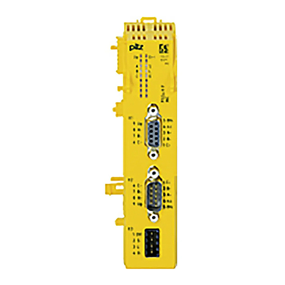
Data transfer per input A, B, C – Status per functional input (Gate, Latch, Status) – Module error – Sensor supply For failsafe and standard applications in system environment B (automation system PSS 4000) Operating Manual PSSu K F INC 1001688-EN-09... - Page 8 Hardware version number 2: Name of compact module 3: Female 9-pin D-Sub connector X1 4: Male 9-pin D-Sub connector X2 5: Male 4-pin connector X3 6: LEDs for status display and module diagnostics Operating Manual PSSu K F INC 1001688-EN-09...
- Page 9 Position Speed Standstill The module PSSu K F INC may be used as a safety component in accordance with the Lifts Directive 95/16/EC in accordance with the requirements of EN 81-1/2:1998+A3:2009, EN 81-20:2015, EN 81-50:2015, EN 81-22:2014 and EN 115-1:2008+A1:2010. The programmable safety system should be installed in a protected environment that meets at least the requirements of pollution degree 2.
- Page 10 Have a good knowledge of the generic and specialist standards applicable to the spe- cific application. 3.2.2 Warranty and liability All claims to warranty and liability will be rendered invalid if The product was used contrary to the purpose for which it is intended Operating Manual PSSu K F INC 1001688-EN-09...
- Page 11 In safety-related applications, please comply with the mission time T in the safety-re- lated characteristic data. When decommissioning, please comply with local regulations regarding the disposal of electronic devices (e.g. Electrical and Electronic Equipment Act). Operating Manual PSSu K F INC 1001688-EN-09...
- Page 12 3 dual-pole, differential inputs A, B, C for connecting an incremental encoder or an en- coder that provides rising edges as counter pulses. 3 single-pole inputs referenced to earth: G, L, S, for special functions Operating modes Incremental encoder Counter Operating Manual PSSu K F INC 1001688-EN-09...
- Page 13 5555 0000 is exceeded (the lower third of the value range). The status information underflow is reset: if FFFF FFFF is exceeded again (overflow). if AAAA FFFF is exceeded (the upper third of the value range). Operating Manual PSSu K F INC 1001688-EN-09...
- Page 14 The module has received a latch pulse. Provided the function is activated, the counter value is copied into the latch memory with a rising edge at input L. e: The counter is disabled because there is a 1 signal at input G. Operating Manual PSSu K F INC 1001688-EN-09...
- Page 15 The module has received a latch pulse. Provided the function is activated, the counter value is copied into the latch memory with a rising edge at input L. e: The counter is disabled because there is a 1 signal at input G. Operating Manual PSSu K F INC 1001688-EN-09...
- Page 16 FFFF FFFF The module issues the result of period length measurement in multiples of 200 ns. Example: The process image of inputs contains 32 The period length is 200 ns x 50 = 10 μs Operating Manual PSSu K F INC 1001688-EN-09...
- Page 17 FFFF FFFF The module always transmits the counter status when the first latch pulse occurs after the function has started. All subsequent latch pulses are ignored until the function is completed and reset. Operating Manual PSSu K F INC 1001688-EN-09...
- Page 18 The module always transmits the counter status when the first zero pulse occurs after the function has started. The counter statuses on all subsequent zero pulses are ignored until the function has been completed and reset. Operating Manual PSSu K F INC 1001688-EN-09...
- Page 19 Double evaluation option: Each rising and each falling edge at channel A increases the counter status. Quadruple evaluation option: Each rising and each falling edge at channel A and channel B increases the counter status. Operating Manual PSSu K F INC 1001688-EN-09...
- Page 20 Transmitting the status via two bits enables simple fault detection: Two redundant bits must always be the same, two diverse bits must always be different, otherwise the trans- mission is faulty. The Double evaluation and Quadruple evaluation options may not be used for failsafe applications. Operating Manual PSSu K F INC 1001688-EN-09...
- Page 21 TRUE: Input L (latch pulse) active/ period length measurement active SetCounter: BOOL FALSE: Do not transfer default counter status TRUE: Transfer default counter status NewCounterValue: Default counter status DWORD Operating Manual PSSu K F INC 1001688-EN-09...
- Page 22 Transmitting the status via two bits enables simple fault detection: Two redundant bits must always be the same, two diverse bits must always be different, otherwise the transmission is faulty. Operating Manual PSSu K F INC 1001688-EN-09...
- Page 23 Electrostatic discharge can damage components. Ensure against discharge before touching the product, e.g. by touching an earthed, conductive sur- face or by wearing an earthed armband. 5.1.1 Dimensions Schematic representation: 30 mm 49,2 mm 1,18" 1,94" Operating Manual PSSu K F INC 1001688-EN-09...
- Page 24 – On the mounting rail, carefully slide the compact module to the left, in parallel to the adjoining module, until you hear the lateral mounting hooks on the adjacent module lock into position [4]. Operating Manual PSSu K F INC 1001688-EN-09...
- Page 25 Installation Schematic representation: Operating Manual PSSu K F INC 1001688-EN-09...
- Page 26 Connection encoder sig- nals Layout Female 9-pin D-Sub con- nector 1: C+ 2: B+ 3: A+ 4: n. c. 5: 0 V counter 6: C- 7: B- 8: A- 9: U (+5 V for sensor) Operating Manual PSSu K F INC 1001688-EN-09...
- Page 27 8: A- 9: U (+5 V for sensor) Connection functional out- puts input devices Layout 4-pin connector 1: 0 V 2: Status S 3: Latch L 4: Gate G n.c. = not connected Operating Manual PSSu K F INC 1001688-EN-09...
-
Page 28: Operation
LED on LED off 7.2.1 Display elements for module diagnostics The module has an LED for displaying module errors ("Err" LED). Meaning Designation Colour Status - - - No error Module is faulty Operating Manual PSSu K F INC 1001688-EN-09... -
Page 29: Display Elements For Counter Status
1 signal at function input G - - - 0 signal at function input L Green 1 signal at function input L - - - 0 signal at function input S Green 1 signal at function input S Operating Manual PSSu K F INC 1001688-EN-09... -
Page 30: Display Elements For Sensor Supply
Status Signal tion - - - No supply voltage Green Supply voltage present Status information The I/O data with status information is described in the chapter entitled "Function Descrip- tion", under "Input/output data". Operating Manual PSSu K F INC 1001688-EN-09... -
Page 31: Technical Details
Time constant of input filter on STATUS signal 50 µs Typ. processing time 0,1 ms Potential isolation between input/output and periphery supply Potential isolation between input/output and voltage for the internal module bus Operating Manual PSSu K F INC 1001688-EN-09... - Page 32 Overvoltage category Pollution degree Protection type In accordance with the standard EN 60529 Housing IP20 Mounting area (e.g. control cabinet) IP54 Mechanical data Material Bottom Connection type D-Sub female connector, D-Sub male connector Operating Manual PSSu K F INC 1001688-EN-09...
- Page 33 A safety function's SIL/PL values are not identical to the SIL/PL values of the units that are used and may be different. We recommend that you use the PAScal software tool to calculate the safety function's SIL/PL values. Operating Manual PSSu K F INC 1001688-EN-09...
-
Page 34: Order Reference
PSSu A LC 0.1 Labelling bracket, scope of supply: 5 pieces 312 966 PSSu A LA0 Labelling strips, laser printable, scope of supply: 1080 pieces 312 958 (10 x DIN A4 sheet, 108 on each) Operating Manual PSSu K F INC 1001688-EN-09... - Page 35 Front cover Support Technical support is available from Pilz round the clock. Americas Australia Scandinavia Brazil +61 3 95600621 +45 74436332 +55 11 97569-2804 Spain Canada Europe +34 938497433 +1 888-315-PILZ (315-7459) Austria Switzerland Mexico +43 1 7986263-0 +41 62 88979-30...
Need help?
Do you have a question about the PSSu K F INC and is the answer not in the manual?
Questions and answers