
Subscribe to Our Youtube Channel
Related Manuals for Pilz PSSu H F PN o


Summary of Contents for Pilz PSSu H F PN o
- Page 1 PSSu H F PN o Decentralised system PSSuniversal I/O Operating Manual-1002522-EN-05...
- Page 2 Preface This document is a translation of the original document. All rights to this documentation are reserved by Pilz GmbH & Co. KG. Copies may be made for internal purposes. Suggestions and comments for improving this documentation will be gratefully received.
-
Page 3: Table Of Contents
Section 5 Installation General installation guidelines Dimensions Installing the head module Section 6 Interfaces Interface configuration 6.1.1 Connection to PROFINET Section 7 Operation Display elements Section 8 Technical Details Section 9 Order reference Operating Manual PSSu H F PN o 1002522-EN-05... -
Page 4: Operating Manual Pssu H F Pn O
Introduction Introduction Validity of documentation This documentation is valid for the PSSu H F PN o module. It is valid until new documenta- tion is published. Please also refer to the following documents: PSSuniversal System Description PSSuniversal Installation Manual This operating manual explains the function and operation, describes the installation and provides guidelines on how to connect the product. - Page 5 Introduction INFORMATION This gives advice on applications and provides information on special fea- tures. Operating Manual PSSu H F PN o 1002522-EN-05...
-
Page 6: Overview
– PSSu E S 4DI-D – PSSu E S PD-D Electronic modules that can be used for input/output: – All failsafe modules (PSSu E F...) – All standard modules (PSSu E S...) Operating Manual PSSu H F PN o 1002522-EN-05... -
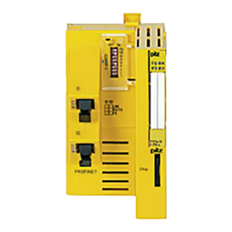
Page 7: Front View
8: Labelling strip with: – Order number – Serial number – Hardware version number – Firmware version number on delivery 9: Field for 2D code 10: Description of head module 11: Chip card slot Operating Manual PSSu H F PN o 1002522-EN-05... -
Page 8: Safety
Updating the firmware can also expand the module's functionality. INFORMATION The module's actual firmware version can only be established using the Firmware Manager on the PSSuniversal Assistant. Operating Manual PSSu H F PN o 1002522-EN-05... -
Page 9: Safety Regulations
In safety-related applications, please comply with the mission time T in the safety-re- lated characteristic data. When decommissioning, please comply with local regulations regarding the disposal of electronic devices (e.g. Electrical and Electronic Equipment Act). Operating Manual PSSu H F PN o 1002522-EN-05... -
Page 10: Function Description
Using the PROFINET project chip card – If the head module already contains a project, you will need to delete this project first (see below). Operating Manual PSSu H F PN o 1002522-EN-05... -
Page 11: Profinet
If a fault occurs, the module switches off the connected failsafe output modules. – The station address is set via a DIP switch. All the project data is stored in the head module. The project data can also be stored on a chip card. Operating Manual PSSu H F PN o 1002522-EN-05... -
Page 12: Dip Switch For Setting The F Address
A station address is set via a combination of the relevant binary coded switches: “F-ADDRESS” DIP switch Meaning Example Switch designation Station address 52 OFF ON INFORMATION Each station address on PROFINET with PROFIsafe must be unique. Operating Manual PSSu H F PN o 1002522-EN-05... -
Page 13: Installation
Electrostatic discharge can damage components. Ensure against discharge before touching the product, e.g. by touching an earthed, conductive sur- face or by wearing an earthed armband. Dimensions 21,6 mm (0.85") 75,5 mm 72,6 mm (2.97") (2.858") Operating Manual PSSu H F PN o 1002522-EN-05... -
Page 14: Installing The Head Module
Install an end bracket to the left of the head module or leave enough space for one. Slot the groove on the head module on to the mounting rail from below [1]. Kopfmodul nach hinten drücken [2], bis es hörbar einrastet. Schematic representation: Operating Manual PSSu H F PN o 1002522-EN-05... -
Page 15: Interfaces
Appropriate design measures should be used to ensure that the plug-in connection is insensitive to in- creased mechanical stress (e.g. through shock, vibration). Such measures include fixed routing und strain relief, for example. Operating Manual PSSu H F PN o 1002522-EN-05... -
Page 16: Operation
312 042 (red) (red) 0000000 HW 000 No supply voltage or fault-free operation 0000 1111 No Ethernet connection 2222 No PROFINET connection RX/TX PSSu H Diagnostic entry present F PN o CHIP PROFINET Operating Manual PSSu H F PN o 1002522-EN-05... - Page 17 Green FS section is running Green Requires the user to confirm via the reset button (e.g. after swapping an FS module) Flash Head module is in PROFIsafe test mode green, 2 Hz Operating Manual PSSu H F PN o 1002522-EN-05...
- Page 18 Yellow Data transfer available RX/TX Attenuation of the optical PSSu H F PN o communication channel in the permitted range Yellow Attenuation of the optical CHIP communication channel too high PROFINET RX/TX Operating Manual PSSu H F PN o 1002522-EN-05...
-
Page 19: Technical Details
2000 m EN 61000-4-2, EN 61000-4-3, EN 61000-4-4, EN 61000-4-5, EN 61000-4-6, EN 61000-6-2, EN 61000-6-4 Vibration In accordance with the standard EN 60068-2-6 Frequency 10 - 150 Hz 0,35 mm Amplitude Acceleration Operating Manual PSSu H F PN o 1002522-EN-05... - Page 20 Mounting area (e.g. control cabinet) IP54 Mechanical data Material Bottom Front Dimensions 128,4 mm Height Width 75,2 mm 79,4 mm Depth Weight 197 g Where standards are undated, the 2012-04 latest editions shall apply. Operating Manual PSSu H F PN o 1002522-EN-05...
-
Page 21: Order Reference
Order reference Order reference Product type Features Order No. PSSu H F PN o Head module with optical PROFIsafe interface, base type 312 042 Operating Manual PSSu H F PN o 1002522-EN-05... - Page 22 Front cover Support Technical support is available from Pilz round the clock. Americas Australia Scandinavia Brazil +61 3 95600621 +45 74436332 +55 11 97569-2804 Spain Canada Europe +34 938497433 +1 888-315-PILZ (315-7459) Austria Switzerland +41 62 88979-30 Mexico +43 1 7986263-0...
Need help?
Do you have a question about the PSSu H F PN o and is the answer not in the manual?
Questions and answers