Table of Contents
Advertisement
Quick Links
STC 160 Head-End Station
Notes on the Assembly Instructions.
As well as this supplementary Assembly
Instructions, the Assembly Instructions for the
STC 160 apply.
GSS
Grundig SAT Systems GmbH
Beuthener Strasse 43
D-90471 Nuremberg
Grundig SAT Syst ms
FM Amplifier
Phone:
+49 (0) 911 / 703 8877
Fax:
+49 (0) 911 / 703 9210
Email:
info@gss.tv
Internet:
www.gss.tv
HRM 225
Advertisement
Table of Contents

Summary of Contents for GSS HRM 225
- Page 1 Grundig SAT Syst ms STC 160 Head-End Station FM Amplifier HRM 225 Notes on the Assembly Instructions. As well as this supplementary Assembly Instructions, the Assembly Instructions for the STC 160 apply. Phone: +49 (0) 911 / 703 8877 Grundig SAT Systems GmbH...
- Page 2 Contents 1 Safety regulations .......................3 2 General information ....................3 2.1 Scope of delivery ..................3 2.2 Meaning of the symbols used .................3 2.3 Technical data .....................4 2.4 Description ....................4 3 Installation .........................5 3.1 Installing the FM amplifier ................5 3.2 Connecting the FM amplifier ................6 4 Setting the FM amplifier ....................7 5 Final procedures ......................8 - 2 -...
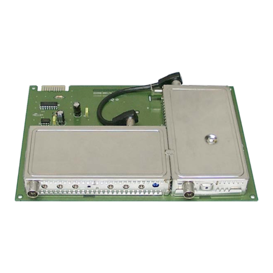
- Page 3 STC 160 head-end station which pertain to this module. When working on the modules, please take measures to protect against ESD! General information 2.1 Scope of delivery 1 FM amplifier HRM 225 1 Attenuator (10 dB) 1 HF connection cables 1 CD (assembly instructions) 1 Brief assembly instructions 2.2 Meaning of the symbols used...
- Page 4 2.3 Technical data The requirements of the following EU directives are met: 73/23/EEC, 89/336/EEC The product fulfils the guidelines and standards for CE labelling. HF input: Frequency range: 87.5 … 108.0 MHz Input level: 45 … 65 dBμV Input impedance: 75 Ω...
- Page 5 You can find the current operating software and the software “BE-Flash” on the website “www.gss.tv”. The FM amplifier HRM 225 is designed exclusively for use in the STC 160 head- end station. Installation Caution – Ensure the head-end station is mounted so it will not be able to vibrate. Avoid, for example, mounting the head-end station onto a lift shaft or any other wall or floor construction that vibrates in a similar way.
- Page 6 • After installing the module close the locking device in the direction of the arrow (fig. 2). Fig. 2 3.2 Connecting the FM amplifier • After setting the FM amplifier (chap. 4) connect its output to one of the inputs of the quad output collector using the attenuator and the IEC / F cable supplied. • Connect input of the FM amplifier to one of the preinstalled F terminals in the rear wall via the cable inlet using an HF cable made on-site (length approx.
- Page 7 After installing the head-end station, retrofitting accessories or installing modules it is necessary to tighten all cable connections, F terminals and cover screws in order to maintain compliance with current EMC regulations and to ensure a reliable operation. Setting the FM amplifier In order to prevent interference, too high signal levels, e.
- Page 8 • Set the output level required for the cable system with level regulator (Fig. 4). • Mount the base plate and the front cover (see STC 160 assembly instruc- tions). Alterations reserved. Technical data E. & O.E. © by GSS GmbH 11012008...


Need help?
Do you have a question about the HRM 225 and is the answer not in the manual?
Questions and answers