
Related Manuals for DMP Electronics 630F


Summary of Contents for DMP Electronics 630F
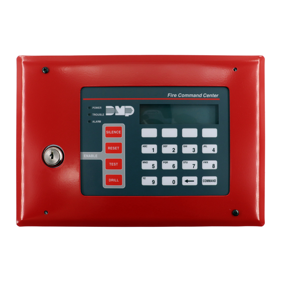
- Page 1 630F Remote Fire Command Center INSTALLATION AND PROGRAMMING GUIDE Fire Command Center POWER TROUBLE ALARM SILENCE RESET ENABLE TEST DRILL COMMAND...
-
Page 3: Table Of Contents
TABLE OF CONTENTS About the 630F ............. 1 Installer Options Menu........14 Four Function Keys .............1 Access the User Menu............. 14 Status LEDs ................1 Programming Keypad Options ........14 Keyswitch ................1 Keypad Options (KPD OPT) ......... 14 Keypad Address ............... 15 Install the 630F ............. - Page 4 Fire Command Center POWER TROUBLE ALARM SILENCE RESET ENABLE TEST DRILL COMMAND Figure 1: 630F Remote Fire Command Center...
-
Page 5: About The 630F
ABOUT THE 630F The 630F Remote Fire Command Center is a 20-key remote fire annunciator with a 32-character LCD display that can be either flush or surface mounted. Four Function Keys Keyswitch The 630F includes four function keys An added 630F feature is a keyswitch that allowing the user to easily silence, reset, enables and disables the four function keys. -
Page 6: Install The 630F
INSTALL THE 630F Mount the Backbox The 630F can either be surface mounted or flush mounted to the wall. The 630F is comprised of three major parts: the backbox (standard or optional surface mount 635), the annunciator membrane backplate, and the trim frame. Refer to Figure 2 as needed. - Page 7 Screw Holes (4) Backbox Trim Frame Membrane Backplate Knockout Surface Mounting Holes (4) Flush Mounting Holes (4) Use to Surface Mount to Wall Use to Flush Mount to Stud Figure 2: Mounting Diagram Digital Monitoring Products, Inc. 630F Installation and Programming Guide...
-
Page 8: Mount And Wire The Membrane Backplate
Refer to Figure 2 for locations of knockouts on backbox for running wires and screw holes on backbox and backplate. Connect a four conductor wire from the 630F backplate terminal strip to panel terminals 7, 8, 9, and 10. See Figure 3. - Page 9 Back of Membrane Backplate Black to 10 Green to 9 4 Position Terminal Strip Yellow to 8 Red to 7 Pre-wired 4-Pin Keyswitch Header Figure 3: Harness Wiring Diagram Digital Monitoring Products, Inc. 630F Installation and Programming Guide...
-
Page 10: Command Center Operation
Device Number DEVICE SETUP At DEVICE NO, enter a device number. DEVICE NO: - For Keypad Bus connections, select a device number from 1-8 for XR150 panels or 1-16 for XR550 panels. 630F Installation and Programming Guide Digital Monitoring Products, Inc. -
Page 11: Device Name
Press CMD until STOP displays. Press a top row select key or STOP area to save programming. If necessary, see the XR150/XR550 Programming Guide (LT-1232) for more information on programming devices. Digital Monitoring Products, Inc. 630F Installation and Programming Guide... - Page 12 Four Function Keys The four function keys allow the user to quickly and easily perform functions on the 630F. The factory installed keyswitch on the left-hand side must be turned to the ENABLE position before the keys activate. The keyswitch does not affect the other keys on the keyboard.
- Page 13 Fire Command Center Status LEDs POWER LCD Display TROUBLE ALARM Function Keys Select Keys SILENCE RESET Keyswitch ENABLE Number Keys TEST DRILL COMMAND Figure 4: 630F Fire Command Center Digital Monitoring Products, Inc. 630F Installation and Programming Guide...
-
Page 14: End-User Options
END-USER OPTIONS The 630F provides three keypad adjustments that the end-user can make. Below is a description of the options and instructions on their operation. The user can also view the keypad model number and address in User Options. To access the User Options portion of the keypad, press and hold the Back Arrow and COMMAND keys for two seconds. -
Page 15: Internal Volume Level
KEYPAD ADDRESS The LCD displays the current keypad address. While in User Options, the user cannot change the keypad address. Press the Back Arrow key to exit the User Options function. Digital Monitoring Products, Inc. 630F Installation and Programming Guide... -
Page 16: Entering Alpha Characters
A, B, and C. Press the first Select key for A, the second Select key for B, and the third Select key for C. See Figure 5. First Letter Second Letter Third Letter Special Letter Figure 5: Entering Alpha Characters 630F Installation and Programming Guide Digital Monitoring Products, Inc. -
Page 17: Entering Non-Alphanumeric Characters
( ) ! ? / & $ ‚ ’ and - . * # for the 0 key. See Figure 6. JKL ? ABC ( DEF ) GHI ! PQR & STU $ MNO / VWX , YZ (space) ’ - . * # Figure 6: Keys with Non-Alpha Characters Digital Monitoring Products, Inc. 630F Installation and Programming Guide... -
Page 18: Installer Options Menu
INSTALLER OPTIONS MENU The 630F also contains Keypad Options and Keypad Diagnostics programs that allow configuration and testing keypad operation. Access the User Menu Hold down the Back Arrow and COMMAND keys for a few seconds. When the SET BRIGHTNESS option displays, enter the code 3577 (INST) then press COMMAND. The display changes to KPD OPT (keypad options), KPD DIAG (keypad diagnostics), and STOP. -
Page 19: Keypad Address
Select key under SUP or UNSUP. An asterisk appears next to the selected option. Note: Unsupervised addresses cannot be used when a Device Fail Output is programmed in Output Options. Digital Monitoring Products, Inc. 630F Installation and Programming Guide... -
Page 20: Default Keypad Message
EM (Emergency), and FI (Fire). Once the panic is enabled, an asterisk displays next to the description. Stop Press CMD until you reach the end of the menu, then select STOP STOP to save the new settings. 630F Installation and Programming Guide Digital Monitoring Products, Inc. -
Page 21: Access Keypad Diagnostics
Verify the correct number displays before testing the next key. Stop Press CMD until you reach the end of the menu, then select STOP STOP to save the new settings. Digital Monitoring Products, Inc. 630F Installation and Programming Guide... -
Page 22: Exit The Installer Options
Exit the Installer Options When done, press the COMMAND key once to return to the Installer Options screen. Press the Select key under STOP to exit the Installer Options function. 630F Installation and Programming Guide Digital Monitoring Products, Inc. -
Page 23: Keypad Bus Wiring Specifications
When voltage is too low, the devices cannot operate properly. For additional information refer to the 710 Installation Sheet (LT-0310) and/or the LX-Bus/Keypad Bus Wiring Application Note (LT-2031). Digital Monitoring Products, Inc. 630F Installation and Programming Guide... -
Page 24: 630F Specifications
16.2 cm H x 22.4 cm W x 6.4 cm D Backbox – Optional Model 635 Surface Mount 6.9” H x 10.3” W x 1.7” D 17.5 cm H x 26.2 cm W x 4.3 cm D 630F Installation and Programming Guide Digital Monitoring Products, Inc. -
Page 25: Compatibility
COMPATIBILITY XR150/XR550 Series Panels Digital Monitoring Products, Inc. 630F Installation and Programming Guide... -
Page 26: Certifications
ANSI/UL 864 Fire Protective Signaling ANSI/UL 985 Household Fire Warning ANSI/UL 1023 Household Burglar ANSI/UL 1076 Proprietary Burglar ANSI/UL 1610 Central Station ULC-S559-04 Equipment for Fire Signal Receiving Centers and Systems 630F Installation and Programming Guide Digital Monitoring Products, Inc. - Page 27 Digital Monitoring Products, Inc. 630F Installation and Programming Guide...
- Page 28 630F Installation and Programming Guide Digital Monitoring Products, Inc.
- Page 29 Digital Monitoring Products, Inc. 630F Installation and Programming Guide...
- Page 30 Information furnished is believed to be accurate and reliable. This information is subject to change without notice. 630F Installation and Programming Guide Digital Monitoring Products, Inc.
- Page 32 LT-0741 1.02 20171 © 2020 Digital Monitoring Products, Inc.
Need help?
Do you have a question about the 630F and is the answer not in the manual?
Questions and answers