Table of Contents
Advertisement
Quick Links
Description
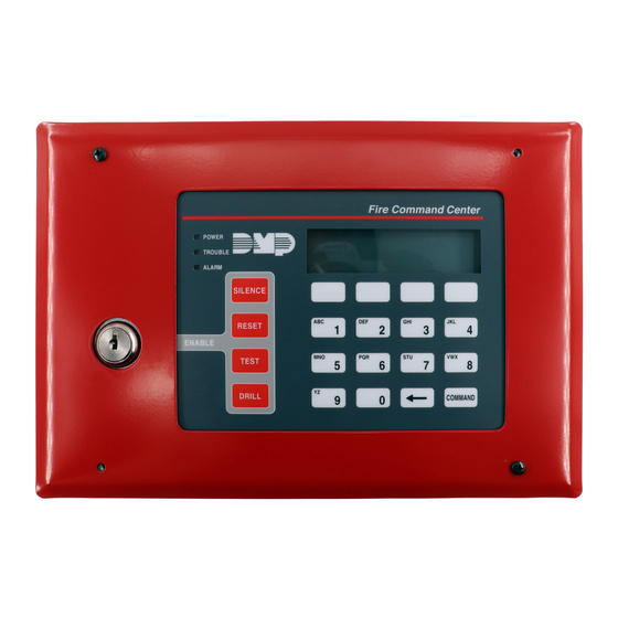
The 630F Remote Fire COMMAND Center is a 20-key remote fire annunciator with a 32-character LCD display that can be
either flush or surface mounted. The 630F includes four function keys allowing the user to easily silence, reset, test, and
drill XR150/XR550 Series panels. An added 630F feature is a keyswitch that enables and disables the four function keys. In
order for the function keys to operate, the factory-installed keyswitch must be enabled. These functions and options can
also be accessed through the User Menu if desired. The 630F also provides three LEDs that indicate system status.
Installation
The 630F can either be flush mounted or surface mounted. The 630F is comprised of three major parts: the backbox
(standard or optional surface mount 635), the annunciator membrane backplate, and the trim frame. The backbox should
be secured to the wall by following the steps below. Refer to Figure 1 as needed.
Surface Mounting the Backbox
The 635 Low-Profile Backbox can be used for surface mount applications.
1. Four 1" screws are needed to attach the backbox to the wall.
2. Screw one screw in each of the four surface mounting holes in the
back of the box.
Note: The 4-hole pattern in the surface mount backbox also fits a 4"
square electrical box. This allows mounting on an electrical box if
necessary.
Flush Mounting the Backbox
Use the included flush mount backbox as shown in Figure 1.
1. Four 1" screws are needed to attach the backbox to the wall stud.
2. The backbox has four mounting holes on both sides. Using the
mounting holes on one side of the backbox, attach the backbox to
a stud. As shown in Figure 1, the backbox tab flush-mounts against
the stud.
For post-sheetrock installation, the flush mount backbox should be
mounted flush against the sheetrock and then attached to the stud
behind using the flush mounting holes.
Mounting the Annunciator Membrane Backplate
Figure 1 is an exploded mounting illustration showing the three
major parts. The dashed lines represent paths for screws. For easier
installation, one knockout is provided on each side and the backbox back.
Use one of the five knockouts for running wires.
After securely mounting the backbox and running the wires as discussed
in the Harness Wirings section, attach the annunciator membrane
backplate to the backbox using the four supplied countersunk 3/8"
Phillips screws. After securing the mounting plate to the backbox, adjust
the mounting plate to the right or left so the LCD display is level. The
four slotted screw holes in the mounting plate corners allow for this
adjustment.
Mounting the Trim Frame
After properly attaching and leveling the mounting
plate, attach the trim frame to the mounting plate for
a finished look. Attach the trim frame using the four
supplied 3/8" black Phillips screws.
Harness Wiring
Connect the 4 wires from the 630F backplate terminal
strip to panel terminals 7, 8, 9, and 10.
COMMAND Center Operation
INTERNAL SPEAKER OPERATION—The speaker emits
standard tones for key presses and system alerts. The
speaker also provides distinct fire siren tones during an
alarm.
LCD BACKLIGHTING—lights to maximum brightness
anytime a key is pressed or the speaker sounds.
Programming
In Device Setup programming, FIRE must be selected for
the 630F address device number. Selecting FIRE enables
the four function keys and the three LEDs to operate.
See the XR150/XR550 Programming Guide (LT-1232)for
more information on programming devices.
INSTALLATION GUIDE
630F Remote Fire COMMAND Center
Flush Mounting Holes
Knockout
Backbox
Surface
Mounting
Holes (4)
Membrane Backplate
Flush
Mounting
Holes
Factory
Installed
Keyswitch
Use 3/8"
Countersunk
Phillips Screws
Use 3/8" Black
Phillips Screws
Figure 1: Exploded Mounting Diagram
Back of Annunciator Membrane Backplate
4 Position Terminal Strip
Back of PCB
4-Pin Header
Figure 2: Harness Wiring Diagram
Stud
Tab
Slotted
Screw
Holes
(4)
Trim Frame
Black to 10
Green to 9
Yellow to 8
Red to 7
Pre-wired
Keyswitch
Advertisement
Table of Contents

Subscribe to Our Youtube Channel
Related Manuals for DMP Electronics 630F


Summary of Contents for DMP Electronics 630F
- Page 1 Description The 630F Remote Fire COMMAND Center is a 20-key remote fire annunciator with a 32-character LCD display that can be either flush or surface mounted. The 630F includes four function keys allowing the user to easily silence, reset, test, and drill XR150/XR550 Series panels.
- Page 2 7/0 Panic Keys The 630F also allows the user to initiate an optional Panic alarm by pressing the 7 and 0 (zero) keys simultaneously for one-half (1/2) second. When enabled, the Fire COMMAND Center annunciator sends a Zone Short message to the panel for the first zone of this keypad address.
- Page 3 PQR & STU $ VWX , Installer Options Menu COMMAND The 630F also contains Keypad Options and Keypad Diagnostics programs that allow - . * # (space) configuration and testing keypad operation. Figure 5: Keys with Non-Alpha Access the User Menu Characters The Installer Options Menu is accessed through the User Options function.
- Page 4 Entry Cards (Display only) 4 DIGIT ENTRY This feature does not operate on the 630F keypad. NO YES CARDS: Arming/Disarming Wait Time (Display only) ALL?: NO YES This feature does not operate on the 630F keypad. DELAY: Accessing Keypad Diagnostics If necessary, refer to Access the User Menu on the previous page.
Need help?
Do you have a question about the 630F and is the answer not in the manual?
Questions and answers