Inovance SV660P Series Hardware Manual
Hide thumbs
Also See for SV660P Series:
- Hardware manual (122 pages) ,
- Troubleshooting manual (95 pages)
Table of Contents
Advertisement
Quick Links
Advertisement
Table of Contents

Subscribe to Our Youtube Channel
Related Manuals for Inovance SV660P Series


Summary of Contents for Inovance SV660P Series
- Page 1 SV660P Series Servo Drive Hardware Guide Data code 19011391 A00...
-
Page 2: Preface
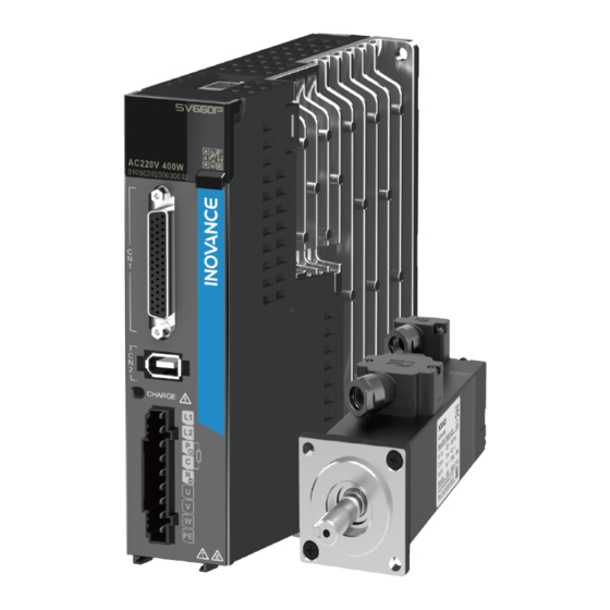
Preface Overview The SV660P series high‑performance AC servo drive covers a power range from 50 W to 7.5 kW. It supports Modbus, CANopen and CANlink communication protocols and carries necessary communication interfaces to work with the host controller for a networked operation of multiple servo drives. -
Page 3: Table Of Contents
Table of Contents T T a a b b l l e e o o f f C C o o n n t t e e n n t t s s Preface ................1 Fundamental Safety Instructions . - Page 4 Table of Contents 3.4.1 Main Circuit Terminal Pin Layout ......... 72 3.4.2 Description of Encoder Terminal (CN2) .
- Page 5 Table of Contents 5.3 UL&cUL Certification ............147 6 Appendix 2 Common EMC Problems and Solutions .
-
Page 6: Fundamental Safety Instructions
3. Use this equipment according to the designated environment requirements. Damage caused by improper use is not covered by warranty. 4. Inovance shall take no responsibility for any personal injuries or property damage caused by improper use. Safety Levels and Definitions Indicates that failure to comply with the notice will result in death or severe personal injuries. - Page 7 Fundamental Safety Instructions Check whether the packing is intact and whether there is damage, water seepage, ● dampness, and deformation before unpacking. Unpack the package by following the unpacking sequence. Do not strike the package ● violently. Check whether there is damage, rust, or injuries on the surface of the equipment and ●...
- Page 8 Fundamental Safety Instructions Read through the user guide and safety instructions before installation. ● Do not install this equipment in places with strong electric or magnetic fields. ● Before installation, check that the mechanical strength of the installation site can bear ●...
- Page 9 Fundamental Safety Instructions Do not connect the input power supply to the output end of the equipment. Failure to ● comply will result in equipment damage or even a fire. When connecting a drive to the motor, check that the phase sequences of the drive and ●...
- Page 10 Fundamental Safety Instructions Do not touch the equipment casing, fan, or resistor with bare hands to feel the ● temperature. Failure to comply may result in personal injuries. Prevent metal or other objects from falling into the equipment during operation. Failure ●...
- Page 11 Fundamental Safety Instructions Disposal Dispose of retired equipment in accordance with local regulations and standards. ● Failure to comply may result in property damage, personal injuries, or even death. Recycle retired equipment by observing industry waste disposal standards to avoid ●...
-
Page 12: Product Information
Product Information Product Information Nameplate and Model Number of the Servo Drive Figure 1‑1 Nameplate and model number of the servo drive ‑11‑... -
Page 13: Nameplate And Model Number Of The Servo Motor
Product Information Figure 1‑2 Encryption of the production serial number Nameplate and Model Number of the Servo Motor ‑ ‑... -
Page 14: Model Number Of Cables
Product Information Figure 1‑3 Nameplate and model number of the servo motor Note SV660P series servo drives can work with the servo motor configured with a 23‑bit single‑ turn or multi‑turn absolute encoder. Model Number of Cables Figure 1‑4 Model number of power cables... - Page 15 Product Information Figure 1‑5 Model number of encoder cables Figure 1‑6 Model number of communication cables ‑ ‑...
-
Page 16: Components
Product Information Components 1.4.1 Servo Drives in Size A (Rated Power: 200 W to 400 W) Figure 1‑7 Components of servo drives in size A (SV660PS1R6I, SV660PS2R8I) Table 1–1 Description of components (SV660PS1R6I, SV660PS2R8I) Description Name CN3, CN4 Connected to RS232 and RS485 host controllers in (communication parallel. - Page 17 Product Information Description Name MODE: Used to switch parameters in sequence. △: Used to increase the value of the blinking bit. ▽: Used to decrease the value of the blinking bit. ◁: Used to shift the blinking bit leftwards. Keys (Hold down: Turning to the next page when the displayed number exceeds five digits) SET: Used to save modifications and enter the next...
-
Page 18: Servo Drives In Size B (Rated Power: 750 W)
Product Information 1.4.2 Servo Drives in Size B (Rated Power: 750 W) Figure 1‑8 Description of servo drive components (SV660PS5R5I) Table 1–2 Description of servo drive components (SV660PS5R5I) Description Name CN3, CN4 (communication Connected to RS232 and RS485 host controllers in parallel. terminals) Used to display the servo drive operating status and set 5‑digit LED display... - Page 19 Product Information Description Name Used to indicate the electric charge is present in the bus capacitor. When this indicator lights up, it indicates the electric charge may be still present in the internal capacitor CHARGE (bus of the servo drive even though the main circuit power voltage indicator) supply is switched off.
-
Page 20: Servo Drives In Size C And Size D (Rated Power: 1.0 Kw To 3.0 Kw)
Product Information 1.4.3 Servo Drives in Size C and Size D (Rated Power: 1.0 kW to 3.0 kW) Figure 1‑9 Components of servo drives in size C and size D (size C: SV660PS7R6I; size D: SV660PS012I) Table 1–3 Description of components (Size C: SV660PS7R6I; size D: SV660PS012I) Description Name CN3, CN4... - Page 21 Product Information Description Name L1C, L2C (control See the nameplate for the rated voltage class. circuit power input terminals) L1, L2, L3 (main Used as the power input terminals for a three‑phase 220 V circuit power input servo drive. See the nameplate for the rated voltage class. terminals) P⊕, D, C (terminals for connecting...
- Page 22 Product Information Figure 1‑10 Components of servo drives in size C and size D (size C: SV660PT3R5I and SV660PT5R4I; size D: SV660PT8R4I and SV660PT012I) Table 1–4 Description of components (Size C: SV660PT3R5I and SV660PT5R4I; size D: SV660PT8R4I and SV660PT012I) Description Name CN3, CN4 Connected to RS232 and RS485 communication command...
- Page 23 Product Information Description Name L1C, L2C (control See the nameplate for the rated voltage class. circuit power input terminals) R, S, T (main circuit Used as the power input terminals for a three‑phase 380 V power input servo drive. See the nameplate for the rated voltage class. terminals) P⊕, D, C (terminals for connecting...
-
Page 24: Servo Drives In Size E (Rated Power: 5.0 Kw To 7.5 Kw)
Product Information 1.4.4 Servo Drives in Size E (Rated Power: 5.0 kW to 7.5 kW) Figure 1‑11 Components of servo drives in size E (SV660PT017I, SV660PT021I, SV660PT026I) Table 1–5 Description of components (SV660PT017I, SV660PT021I, SV660PT026I) Description Name CN3, CN4 Connected to RS232 and RS485 host controllers in (communication parallel. -
Page 25: Servo Motors In Flange Sizes 40/60/80
Product Information Description Name L1C, L2C (control See the nameplate for the rated voltage class. circuit power input terminals) Used as the power input terminals for a three‑phase R, S, T (main circuit 380 V servo drive. See the nameplate for the rated power input terminals) voltage class. - Page 26 Product Information Table 1–6 Components of terminal‑type motors Name Encoder socket Power socket Mounting flange face Mounting screw through‑hole Shaft extension (with key) Figure 1‑13 Components of lead wire‑type motors Table 1–7 Components of lead wire‑type motors Name Power cable connector Power cable Mounting flange face Output shaft...
-
Page 27: Servo Motors In Flange Sizes 100/130/180
Product Information 1.4.6 Servo Motors in Flange Sizes 100/130/180 Figure 1‑14 Components of servo drives in flange sizes 100/130/180 Table 1–8 Components of servo drives in flange sizes 100/130/180 Name Encoder connector Power cable connector Mounting flange face Mounting screw through‑hole Shaft extension (with key) ‑... -
Page 28: Installation
“ Figure 2–1 ” on page 28 Check whether the product delivered is in good condition. If Check whether the there is any part missing or damaged, contact Inovance or your product is intact. supplier immediately. ‑27‑... - Page 29 Installation Table 2–1 Dimensions of the outer packing box Outer Width Outer Height Outer Depth Specifications (mm) (mm) (mm) Size A 250.0 90.0 (SV660PS1R6I, SV660PS2R8I) Size B 225.0 205.0 (SV660PS5R5I) Size C (SV660PS7R6I, SV660PT3R5I, 235.0 105.0 215.0 T5R4I) Size D 235.0 130.0 225.0...
-
Page 30: Installation Environment
● Altitude For altitudes above 1000 m, derate 1% for every additional 100 m. ● For altitudes above 2000 m, contact Inovance. ● Mounting/Operating temperature: 0℃ to 55℃ ● For temperatures between 0℃ to 45℃, derating is not required. For temperatures above 45℃, derate 2% for every additional 1℃. -
Page 31: Installation Clearance
Installation Requirement Item IP rating IP20 Pollution Degree 2 and below Install the servo drive in a place that meets the following requirements: Free from direct sunlight, dust, corrosive gas, explosive and ● inflammable gas, oil mist, vapor, water drop, and salty element Insusceptible to vibration (away from equipment that may ●... - Page 32 Installation Figure 2‑3 Clearance for side‑by‑side installation Servo drives in size A and size B (rated power: 200 W to 750 W) support compact installation, in which a clearance of at least 1 mm (0.04 in.) must be reserved between every two servo drives.
-
Page 33: Installation Dimensions
Installation Servo drives in sizes C, D and E (rated power: 1.0 kW to 7.5 kW) support zero‑clearance installation between every two servo drives, without the need for derating. Figure 2‑5 Zero‑clearance installation 2.1.4 Installation Dimensions Servo drives in size A (rated power: 200 W to 400 W): SV660PS1R6I, SV660PS2R8I Figure 2‑6 Dimension drawing of servo drives in size A ‑... - Page 34 Installation Servo drives in size B (rated power: 750 W): SV660PS5R5I Figure 2‑7 Dimension drawing of servo drives in size B Servo drives in size C (rated power: 1.0 kW to 1.5 kW): SV660PS7R6I, SV660PT3R5I, and SV660PT5R4I Figure 2‑8 Dimension drawing of servo drives in size C ‑33‑...
- Page 35 Installation Servo drives in size D (rated power: 1.5 kW to 3.0 kW): SV660PS012I, SV660PT8R4I, and SV660PT012I Figure 2‑9 Dimension drawing of servo drives in size D Servo drives in size E (rated power: 5.0 kW to 7.5 kW): SV660PT017I, SV660PT021I, and SV660PT026I Figure 2‑10 Dimension drawing of servo drives in size E ‑...
-
Page 36: Installation Precautions
Installation 2.1.5 Installation Precautions Table 2–3 Installation precautions Description Item Install the servo drive vertically upward to facilitate heat ● dissipation. For installation of multiple servo drives inside the cabinet, install them side by side. For dual‑row installation, install an air guide plate. Make sure the servo drive is installed vertically to the wall. -
Page 37: Installation Instructions
Installation Description Item As shown in the figure below, route the servo drive cables downwards to prevent liquids from flowing into the servo drive along the cables. Routing Insert the dust‑proof cover into the communication port (CN3/ CN4) not in use. This is to prevent unwanted objects, such as solids or liquids, from falling into the servo drive and resulting in faults. -
Page 38: Installing The Servo Motor
Check whether the packing box is intact. If the packing box is damaged, contact your supplier immediately. Check whether the product delivered is in good condition. If Check whether the product there is any part missing or damaged, contact Inovance or is intact. your supplier immediately. ‑37‑... -
Page 39: Installation Environment
The maximum altitude is 5000 m. Derating is not required for altitudes above 1000 m. Altitude For altitudes above 1000 m, derate 1% for every additional 100 m. For altitudes above 2000 m, contact Inovance. Ambient 0°C to 40℃ (non‑freezing) temperature Storage ‑20°C to +60°C (Peak temperature: 80°C for 72 hours) -
Page 40: Installation Dimensions
Installation 2.2.3 Installation Dimensions Dimension drawings of MS1H1 series motors Figure 2‑12 Dimension drawing of terminal‑type motors Figure 2‑13 Dimension drawing of lead wire‑type motors ‑39‑... - Page 41 Installation Motor Model Unit: mm (in.) MS1H1‑05B30CB‑ 25±0.5 2‑φ4.5 2.5±0.5 0.5±0.35 A330Z(‑S) (2.56) MS1H1‑05B30CB‑ 96.00 (1.57) (0.98±0.02) (1.81) (0.08‑φ0.18) (1.34) (0.20) (0.10±0.02) (0.02±0.01) A332Z(‑S) (3.78) MS1H1‑10B30CB‑ 77.5 25±0.5 2‑φ4.5 2.5±0.5 0.5±0.35 A330Z(‑S) (3.05) MS1H1‑10B30CB‑ (1.57) (0.98±0.02) (1.81) (0.08‑φ0.18) (1.34) (0.20) (0.10±0.02) (0.02±0.01) A332Z(‑S)
- Page 42 The tightening tension for terminal screws must be between 0.19 N·m to 0.21 ● N·m, exceeding of which may damage the terminal. For dimension drawings of motor models ending with "‑S", contact Inovance ● technical support. Dimension drawings of MS1H2 series motors Figure 2‑14 Dimension drawing of MS1H2 series motors...
- Page 43 Installation Motor Model Unit: mm (in.) MS1H2‑ 240.5 169.5 218.5 25C30CD‑ 45±1 4‑φ7 5±0.3 (9.47) (6.67) (8.60) 2.5±0.75 A331Z (1.77±0 (0.16‑ (0.20± MS1H2‑ (3.94) (4.53) (3.46) (2.91) (0.39) (0.10±0.03) (3.74) .04) φ0.28) 0.01) 25C30CD‑ (11.42) (7.01) (10.59) A334Z(‑S4) MS1H2‑ 209.5 188.5 30C30CD‑...
- Page 44 Installation Motor Power Weight Model Side (Power Connec Encoder Brake tor Model Side Unit: kg (lb.) Unit: mm (in.) Side Included) MS1H2‑ 5.11 10C30CB( (11.27) M8x16 D)‑A331Z ‑0.2 MS1H2‑ (0.94) (M8x0.63) (1.42) (0.78 ‑0.01 ) (0.31) (0.31) (0.28) 6.41 10C30CB( (14.13) D)‑A334Z MS1H2‑...
- Page 45 Installation Note Values inside the parentheses "()" are in British units. ● The tightening tension for terminal screws must be between 0.19 N·m to 0.21 ● N·m, exceeding of which may damage the terminal. Motor models ending with "‑S4" represents the duty type S4, indicating the motor ●...
- Page 46 Installation Motor Model Unit: mm (in.) MS1H3‑ 18C15CD‑ 55±1 4‑Φ9 (7.13) (6.30) 107.5 0.5±0.75 A331Z (2.17±0 (0.16‑ MS1H3‑ (5.12) (5.71) (4.06) (4.23) (2.91) (0.55) (0.16) (0.02±0.03) (4.33) .04) Φ0.35) 18C15CD‑ (8.54) (7.72) A334Z MS1H3‑ 3.2±0. 29C15CD‑ 79±1 4‑φ13.5 (7.76) (5.35) (6.97) 0.3±0.75 114.3...
- Page 47 Installation Power Weight Side (Power Motor Connector Encoder Unit: kg Brake Model Model Side Unit: mm (in.) (lb.) Side Included) MS1H3‑ 85B15CB( (15.43) M6x20 D)‑A331Z ‑0.2 MS1H3‑ (0.87) (M6x0.79) (1.42) (0.71 ‑0.01 ) (0.31) (0.31) (0.28) 85B15CB( (17.64) D)‑A334Z MS1H3‑ 13C15CB( (17.64) M6x20...
- Page 48 Installation Note Values inside the parentheses "()" are in British units. ● The tightening tension for terminal screws must be between 0.19 N·m to 0.21 ● N·m, exceeding of which may damage the terminal. Dimension drawings of MS1H4 series motors Figure 2‑16 Dimension drawing of terminal‑type motors Figure 2‑17 Dimension drawing of lead wire‑type motors ‑47‑...
- Page 49 Values inside the parentheses "()" are in British units. ● The tightening tension for terminal screws must be between 0.19 N·m to 0.21 ● N·m, exceeding of which may damage the terminal. For dimension drawings of motor models ending with "‑S", contact Inovance ● technical support. ‑ ‑...
-
Page 50: Installation Precautions
Installation 2.2.4 Installation Precautions Description Item Wipe up the anti‑rust agent applied at the motor shaft extension before Rust‑proof installing the servo motor, and then take rust‑proof measures. treatment Do not strike the shaft extension during installation. Failure to ● comply will damage the encoder. - Page 51 Installation Description Item Installation The servo motor can be installed horizontally or vertically. direction Do not submerge the motor/cable in water or oil. ● Confirm the IP rating of the servo motor when the motor is to be ● used in a place with water drops (excluding the shaft opening). Install the motor with its connecting terminals facing downwards ●...
-
Page 52: Installing The Optional Parts
Installation Description Item Do not bend or pull the cable with excessive force, especially the signal Stress of wires whose conductors are only 0.2 mm or 0.3 mm in thickness. cables Pay attention to the following precautions Ensure there are no unwanted objects such as waste or sheet metal ●... -
Page 53: Instructions For Installing The Ac Input Reactor
Installation 2.3.2 Instructions for Installing the AC Input Reactor Figure 2‑18 Installing the AC input reactor 2.3.3 Instructions for Installing the EMC Filter Figure 2‑19 Installing the EMC filter ‑ ‑... -
Page 54: Instructions For Installing Magnetic Ring And Ferrite Clamp
Installation 2.3.4 Instructions for Installing Magnetic Ring and Ferrite Clamp Figure 2‑20 Installing the magnetic ring ‑53‑... - Page 55 Installation Figure 2‑21 Installing the ferrite clamp ‑ ‑...
-
Page 56: Wiring
Wiring Wiring Wiring Precautions Read through the safety instructions in Chapter "Fundamental Safety Instructions". Failure to comply may result in serious consequences. Do not use the power from IT system for the drive. Use the power from TN/TT ● system for the drive. Failure to comply may result in an electric shock. Connect an electromagnetic contactor between the input power supply and the ●... - Page 57 Wiring The specification and installation of external cables must comply with applicable ● local regulations. Observe the following requirements when the servo drive is used on a vertical axis. ● Set the safety device properly to prevent the workpiece from falling upon —...
-
Page 58: System Wiring Diagram
Wiring Locations with strong electric field or magnetic field — — Locations with radioactive rays — — System Wiring Diagram Figure 3‑1 Wiring example of a single‑phase 220 V system The servo drive is directly connected to an industrial power supply, with no ●... - Page 59 Wiring For the sake of safety, install a residual current device (RCD) to provide protections against overload and short circuit or a specialized RCD to protect the grounding cable. Do not start or stop the motor by using the electromagnetic contactor. As a high‑ ●...
- Page 60 Wiring Figure 3‑2 Wiring example of a three‑phase 220 V system The servo drive is directly connected to an industrial power supply, with no ● isolation such as a transformer. A fuse or circuit breaker therefore must be connected to the input power supply to prevent electric shock in the servo system. For the sake of safety, install a residual current device (RCD) to provide protections against overload and short circuit or a specialized RCD to protect the grounding cable.
- Page 61 Wiring When connecting an external power supply to the control circuit or a 24 VDC ● power supply, pay attention to the power capacity as insufficient power capacity will lead to insufficient supply current, resulting in failure of the servo drive or the brake.
- Page 62 Wiring Figure 3‑3 Wiring example of a three‑phase 380 V system The servo drive is directly connected to an industrial power supply, with no ● isolation such as a transformer. A fuse or circuit breaker therefore must be connected to the input power supply to prevent electric shock in the servo system. For the sake of safety, install a residual current device (RCD) to provide protections against overload and short circuit or a specialized RCD to protect the grounding cable.
- Page 63 Wiring will lead to insufficient supply current, resulting in failure of the servo drive or the brake. This is especially true when the power supply is used to power up multiple servo drives or brakes. The brake must be powered up by a 24 VDC power supply that matches the motor model and meets the brake power requirements.
-
Page 64: Wiring Diagram For Different Control Modes
Wiring Wiring Diagram for Different Control Modes 3.3.1 Wiring Diagram for Position Control Mode Figure 3‑4 Wiring in the position control mode ‑63‑... - Page 65 Wiring Note [1] The range of the internal +24 V power supply is 20 V to 28 V, with maximum ● operating current being 200 mA. [2] DI8 and DI9 are high‑speed DIs that must be used according to their functions ●...
-
Page 66: Wiring Diagram For Torque Control Mode
Wiring 3.3.2 Wiring Diagram for Torque Control Mode Figure 3‑5 Wiring in the torque control mode ‑65‑... - Page 67 Wiring Note [1] The range of the internal +24 V power supply is 20 V to 28 V, with maximum ● operating current being 200 mA. [2] DI8 and DI9 are high‑speed DIs that must be used according to their functions ●...
-
Page 68: Terminal Layout Of The Servo Drive
Wiring Terminal Layout of the Servo Drive Servo drives in size A (rated power: 200 W to 400 W): SV660PS1R6I and SV660PS2R8I Figure 3‑6 Terminal pin layout of servo drives in size A ‑67‑... - Page 69 Wiring Servo drives in size B (rated power: 750 W): SV660PS5R5I Figure 3‑7 Terminal pin layout of servo drives in size B ‑ ‑...
- Page 70 Wiring Servo drives in size C and size D (rated power: 1.0 kW to 1.5 kW): size C: SV660PS7R6I; size D: SV660PS012I Figure 3‑8 Terminal pin layout of servo drives in size C (SV660PS7R6I) and size D (SV660PS012I) ‑69‑...
- Page 71 Wiring Servo drives in size C and size D (rated power: 1.0 kW to 3.0 kW): size C: SV660PT3R5I and SV660PT5R4I; size D: SV660PT8R4I and SV660PT012I Figure 3‑9 Terminal pin layout of servo drives in size C (SV660PT3R5I, SV660PT5R4I) and size D (SV660PT8R4I, SV660PT012I) ‑...
- Page 72 Wiring Servo drives in size E (rated power: 5.0 kW to 7.5 kW): SV660PT017I, SV660PT021I, and SV660PT026I Figure 3‑10 Terminal pin layout of servo drives in size E ‑71‑...
-
Page 73: Main Circuit Terminal Pin Layout
Wiring 3.4.1 Main Circuit Terminal Pin Layout Servo drives in size A (rated power: 200 W to 400 W): SV660PS1R6I and SV660PS2R8I Figure 3‑11 Main circuit terminal pin layout of servo drives in size A Table 3–1 Description of main circuit terminal pins of servo drives in size A Description Name L1, L2... - Page 74 Wiring Servo drives in size B (rated power: 750 W): SV660PS5R5I Figure 3‑12 Main circuit terminal pin layout of servo drives in size B Table 3–2 Description of main circuit terminal pins of servo drives in size B Description Name See the nameplate for the rated voltage class.
- Page 75 Wiring Servo drives in size C and size D (rated power: 1.0 kW to 1.5 kW): SV660PS7R6I and SV660PS012I Figure 3‑13 Main circuit terminal pin layout of servo drives in size C (SV660PS7R6I) and size D (SV660PS012I) Table 3–3 Description of main circuit terminal pins of servo drives in size C (SV660PS7R6I) and size D (SV660PS012I) Description Name...
- Page 76 Wiring Description Name U, V, W (terminals for Connected to U, V, and W phases of the servo motor. connecting the servo motor) Connected to the grounding terminal of the motor for Motor grounding grounding purpose. terminal Servo drives in size C and size D (rated power: 1.0 kW to 3.0 kW): SV660PT3R5I, SV660PT5R4I, SV660PT8R4I, and SV660PT012I Figure 3‑14 Main circuit terminal pin layout of servo drives in size C (SV660PT3R5I, SV660PT5R4I) and size D (SV660PT8R4I, SV660PT012I)
- Page 77 Wiring Description Name P⊕, NΘ Used by the common DC bus for multiple servo drives. (DC bus terminals) P⊕, D, C (terminals for If an external regenerative resistor is needed, connect it connecting between terminals P⊕ and C. Servo drives in size C and external size D are equipped with the built‑in regenerative regenerative...
-
Page 78: Description Of Encoder Terminal (Cn2)
Wiring Table 3–5 Description of main circuit terminal pins of servo drives in size E Description Name L1C, L2C (control circuit See the nameplate for the rated voltage class. power input terminals) R, S, T (main circuit power See the nameplate for the rated voltage class. input terminals) U, V, W (terminals for... -
Page 79: Description Of The Control Terminal (Cn1)
Wiring Description Name Encoder signal PS‑ Enclosure Shield 3.4.3 Description of the Control Terminal (CN1) Figure 3‑17 Control terminal pin layout of servo drives in sizes A and B ‑ ‑... - Page 80 Wiring Figure 3‑18 Control terminal pin layout of servo drives in sizes C, D, and E Note CN1: Plastic housing of plug on cable side: DB25P (manufacturer: SZTDK), black ● housing Core: HDB44P male solder (manufacturer: SZTDK) It is recommended to use cables of 24AWG to 26AWG. ●...
- Page 81 Wiring Table 3–7 Description of position reference input signals Signal Name Pin No. Function PULSE+ Low‑speed pulse Pulse input form: reference input mode: Direction+Pulse PULSE‑ ● Differential drive Quadrature pulse of SIGN+ ● ● input phases A and B SIGN‑...
-
Page 82: Description Of Communication Terminals (Cn3/Cn4)
Wiring Table 3–9 Specifications of encoder frequency‑division output signals Signal Default Pin No. Function Name Function PAO+ Phase A frequency‑ Quadrature division output PAO‑ frequency‑division signal pulse output PBO+ Phase B frequency‑ signals of phases A division output and B PBO‑... -
Page 83: Connecting The Power Supply (Rst)
● on or off frequently within 1s, Er.740/Er.136/Er.430 may occur (see Chapter "Troubleshooting" in SV660P Series Servo Drive Commissioning Guide for details). In this case, power on the servo drive again after waiting for the specified ON/OFF interval. If frequent ON/OFF control is needed, keep an ON/OFF interval of at least 1 min. -
Page 84: Main Circuit Wiring Requirements
Wiring Use a grounding cable of the same cross‑sectional area as the main circuit cable. If ● the cross‑sectional area of the main circuit cable is less than 1.6 mm , use a grounding cable with a cross‑sectional area of 2.0 mm Do not power on the servo drive if terminal screws or cables are loose. -
Page 85: Recommended Cable Specifications And Models
Wiring When using an electric screwdriver to tighten terminal screws, set the electric ● screwdriver to low speed to prevent damage to the terminal screws. Tighten the terminal screws with an angle not higher than 5°. Failure to comply ● may damage the terminal screws. - Page 86 Wiring Recommended PVC Cable Model (at 40℃) Rated Input Servo Drive Servo Drive L1, L2/L1, Tightening R, S, T Cable Lug Current L2, L3 Series Model Torque (N·m) SV660PS7 ‑ ‑ ‑ Size C SV660P Size D 12.8 ‑ ‑ ‑...
- Page 87 Wiring MS1H1/H4 05B–10C (Applicable to Motors with Rated Output of 50 W to 1 kW) Internal structure and conductor colors Fill in "X.X" in the model number with designated cable length. Table 3–14 Specifications of motor output cables MS1H2 10C–50C (Applicable to Motors with Rated Output of 1 kW to 5 kW)/MS1H3 85B–18C (Applicable to Motors with Rated Output of 850 W to 1.8 kW) Oil‑resistant shielded Cable type...
- Page 88 Wiring Table 3–15 Specifications of motor output cables MS1H3 29C–75C (Applicable to Motors with Rated Output of 2.9 kW to 7.5 kW) Oil‑resistant shielded Cable type Regular cable Flexible cable flexible cable S6‑L‑M/B***‑X.X S6‑L‑M/B***‑X.X‑T S6‑L‑M/B***‑X.X‑TS Cable model UL2586 (rated UL2586 (rated UL2586 (rated temperature: 105℃) temperature: 105℃)
-
Page 89: Wiring Of The Power Supply
“ Cable requirements ” on page Note If the recommended cable specifications for peripheral devices or optional parts exceed the applicable cable specification range, contact Inovance. 3.5.4 Wiring of the Power Supply Single‑phase 220 V models: SV660PS1R6I, SV660PS2R8I, SV660PS5R5I, ●... - Page 90 Wiring Figure 3‑21 Main circuit wiring of single‑phase 220 V models Note 1KM: Electromagnetic contactor; 1Ry: Relay; 1D: Flywheel diode ● The DO is set as alarm output (ALM+/‑). When the servo drive alarms, the power ● supply is cut off automatically. The built‑in regenerative resistor is not available in models SV660PS1R6 and SV660PS2R8.
- Page 91 Wiring Figure 3‑22 Main circuit wiring of three‑phase 220 V models Note 1KM: Electromagnetic contactor; 1Ry: Relay; 1D: Flywheel diode ● The DO is set as alarm output (ALM+/‑). When the servo drive alarms, the power ● supply is cut off automatically and the alarm indicator lights up. Three‑phase 380 V models: SV660PT3R5I, SV660PT5R4I, SV660PT8R4I, ●...
-
Page 92: Wiring Of External Emc Filter
Wiring Figure 3‑23 Main circuit wiring of three‑phase 380 V models Note 1KM: Electromagnetic contactor; 1Ry: Relay; 1D: Flywheel diode ● The DO is set as alarm output (ALM+/‑). When the servo drive alarms, the power ● supply is cut off automatically and the alarm indicator lights up. 3.5.5 Wiring of External EMC Filter Install the filter near the input terminals of the drive. -
Page 93: Grounding And Wiring
Wiring Figure 3‑24 Installing the filter Keep the lead wire of the motor cable shield as short as possible, with its width (b in the following figure) not shorter than 1/5 of its length (a in the following figure). Figure 3‑25 Lead‑out of the motor cable shield 3.5.6 Grounding and Wiring Observe the following requirements to ensure a proper grounding of the servo drive. - Page 94 Wiring To prevent electric shocks, ground the grounding terminal properly. Observe ● related national or regional regulations during wiring. To prevent electric shocks, ensure the protective grounding conductor complies ● with technical specifications and local safety standards. Keep the length of the grounding cable as short as possible.
- Page 95 Wiring It is recommended to install the drive to a conductive metal surface. Ensure the ● whole conductive bottom of the drive is connected properly to the mounting face. Tighten the grounding screw with specified tightening torque to prevent the ●...
- Page 96 Wiring Description ⑦ Ground the motor enclosure. Note: The main circuit terminal layout varies with different models and is subject to the physical product. Multi-drive grounding Side‑by‑side installation of multiple drives: Table 3–17 Multi‑drive grounding Description Connect the main circuit input PE terminal to the grounding copper busbar of ①...
- Page 97 Wiring the disturbance source, and install devices into corresponding areas based on the requirements listed in the following table. Table 3–18 Wiring requirements Wiring requirements Install the control devices and drive devices into two separate cabinets. For installation involving multiple cabinets, use the grounding cable with a cross‑sectional area of at least 16 mm to connect the cabinets.
-
Page 98: Connecting The Motor (Uvw)
Wiring Recommended grounding cable lug for the main circuit Table 3–19 Recommended grounding cable lug for the main circuit Servo Drive Model SV660P****I SV660PS1R6I TVR 2‑4 Size A SV660PS2R8I TVR 2‑4 Size B SV660PS5R5I TVR 2‑4 SV660PS7R6I TVR 2‑4 Size C SV660PT3R5I TVR 2‑4 SV660PT5R4I... - Page 99 [1] The flange size refers to the width of the mounting flange. ● Power cable colors are subject to the actual product. All cable colors mentioned in ● this guide refer to Inovance cable colors. The wiring diagram for a lead wire‑type motor is shown in the following figure. ● ‑...
- Page 100 [1] The flange size refers to the width of the mounting flange. ● Power cable colors are subject to the actual product. All cable colors mentioned in ● this guide refer to Inovance cable colors. The following table describes the connector for high‑power motor power cables. ● ‑99‑...
-
Page 101: Connecting The Encoder (Cn2)
● Power cable colors are subject to the actual product. All cable colors mentioned in ● this guide refer to Inovance cable colors. Connecting the Encoder (CN2) 3.7.1 Installing Absolute Encoder Battery Box The optional S6‑C4 battery box contains the following items: One plastic body ●... - Page 102 Wiring Installing the battery box Figure 3‑29 Installing the battery box (bottom view) Removing the battery box The battery may generate leakage liquid after long‑term use. Replace it every two years. Remove the battery box in steps shown in the preceding figure, but in the reverse order.
- Page 103 Wiring Improper use of the battery may result in liquid leakage which corrodes the components or leads to battery explosion. Observe the following precautions during use: Insert the battery with polarity (+/‑) placed correctly. ● Leaving an idled or retired battery inside the device may lead to electrolyte ●...
- Page 104 Wiring Table 3–25 Description of the absolute encoder battery Rated Values Battery Item Minimum Typical Maximum Condition Specifications Value Value Value External battery In standby state voltage (V) Circuit fault In standby state ‑ ‑ voltage (V) Battery alarm Output: 3.6 V, 2.85 3.15 ‑...
-
Page 105: Absolute Encoder Cable Connection
Wiring Table 3–26 Design life of the absolute encoder battery Item Schedule 1 Schedule 2 Working Days in Different Operating Conditions in 1 Year T1 (h) T2 (h) T3 (h) 15.9 Capacity consumed in 1 year = (8 h x 2 uA + 0.1 h x 80 uA + 15.9 h x 10 uA) x 313 + (0 h x 2 uA + 0 h x 80 uA +24 h x 10 uA) x 52 ≈... - Page 106 The encoder cable color is subject to the color of the actual product. Cable colors ● mentioned in this guide all refer to Inovance cables. Lead wires of the battery box: Figure 3‑32 Description of the lead wire color of the battery box...
- Page 107 Wiring Note Store the battery in environments compliant with the required temperature range ● and ensure reliable contact and sufficient battery power. Failure to comply may result in encoder data loss. Model of the battery box (battery included): S6‑C4 ● Table 3–27 Terminal‑type motor encoder cable connector Terminal Pin Layout Applicable Motor...
- Page 108 Wiring Table 3–28 Lead wire‑type motor encoder cable connector (9‑pin connector) Terminal Pin Layout Applicable Motor Outline Drawing of the Connector Signal Flange Size Type Pin No. Color Name Twisted pair Orange Blue Twisted Servo pair Purple PS‑ drive side Enclo ‑...
-
Page 109: Connecting The Control Signal (Cn1)
Wiring Table 3–29 Absolute encoder cable connector (MIL‑DTL‑5015 series 3108E20‑29S aviation connector) Applicable Terminal Pin Layout Motor Outline Drawing of the Connector Signal Flange Size Type Pin No. Color Name Twisted pair Orange Blue Twisted pair Purple PS‑ Servo drive side Enclosure ‑... -
Page 110: Position Reference Input Signals
Wiring Figure 3‑33 Diagram of shielded twisted pairs I/O signal layout I/O signals include DI/DO signals and relay output signals. Observe the following requirement during control circuit wiring: Route the control circuit cables and main circuit cables or other power cables through different routes with a distance of at least 30 cm. - Page 111 Wiring Open‑collector mode ● ① For use of the internal 24 V power supply of the servo drive: ‑ ‑...
- Page 112 Wiring Wrong: Pin 14 (COM‑) is not connected and a closed‑loop circuit cannot be formed. ② For use of an external power supply: Scheme 1: Using the built‑in resistor (recommended) ■ ‑111‑...
- Page 113 Wiring Scheme 2: Using the external resistor ■ ‑ ‑...
- Page 114 Wiring Select resistor R1 based on the following formula. Table 3–31 Recommended resistance of R1 Voltage Resistance of R1 Power of R1 24 V 2.4 kΩ 0.5 W 0.5 W 12 V 1.5 kΩ ‑113‑...
- Page 115 Wiring The following figures show examples of improper wiring. ■ Improper wiring 1: The current limiting resistor is not connected, resulting in ■ terminal burnout. Wrong wiring 2: Multiple terminals share the same current limiting resistor, ■ resulting in pulse receiving error. Wrong wiring 3: The SIGN port is not connected, preventing these two ports ■...
- Page 116 Wiring Figure 3‑34 Wrong wiring 4: Terminals are connected incorrectly, resulting in terminal ■ burnout. Wrong wiring 5: Multiple terminals share the same current limiting resistor, ■ resulting in pulse receiving error. ‑115‑...
- Page 117 Wiring High-speed pulse reference input High‑speed reference pulses and signs on the host controller side can be outputted to the servo drive through the differential drive only. ‑ ‑...
-
Page 118: Di/Do Signals
Wiring The differential input must be 5 V. Otherwise, unstable pulse input will occur on the servo drive, resulting in the following situations: Pulse loss during pulse input ● Reference inverted during reference direction input ● Connect 5V GND of the host controller to the GND of the servo drive to reduce noise interference. - Page 119 Wiring The host controller provides open‑collector output. ● For use of an internal 24 V power supply of the servo drive ■ ‑ ‑...
- Page 120 Wiring For use of an external power supply ■ Note PNP and NPN input cannot be applied in the same circuit. DO circuit The circuits for DO1 to DO5 are the same. The following description takes DO1 circuit as an example. The host controller provides relay input.
- Page 121 Wiring Note When the host controller provides relay input, a flywheel diode must be installed. Other‑ wise, the DO terminals may be damaged. The host controller provides optocoupler input. ● ‑ ‑...
-
Page 122: Encoder Frequency-Division Output Signals
Wiring Note The maximum permissible voltage and current capacity of the optocoupler output circuit inside the servo drive are as follows: Maximum voltage: 30 VDC ● Maximum current: DC 50 mA ● 3.8.4 Encoder Frequency-Division Output Signals For details on encoder frequency‑division output signals, see “... - Page 123 Wiring The encoder phase Z frequency‑division output circuit supports open‑collector signal output. Generally, this circuit serves to provide feedback signals to the host controller in a position control system. Use an optocoupler circuit, relay circuit, or bus receiver circuit on the host controller side to receive feedback signals. ‑...
-
Page 124: Wiring Of The Brake
Wiring To reduce noise interference, use shielded twisted pairs to connect the 5V GND of the host controller to the GND of the servo drive. The maximum permissible voltage and current capacity of the optocoupler output circuit inside the servo drive are as follows: Maximum voltage: 30 VDC ●... - Page 125 When deciding the length of the motor brake cable, take the voltage drop caused by cable resistance into consideration. The input voltage must be at least 21.6 V to enable the brake to work properly. The following table lists brake specifications of Inovance MS1 series servo motors. ‑ ‑...
- Page 126 Wiring Table 3–32 Brake specifications Supply Holding Exciting Coil Resistance Release Time Apply Time Backlash Voltage Torque Current Motor Model (Ω)±7% (ms) (ms) (°) (VDC) (N·m) ±10% MS1H1‑05B/10B 0.32 94.4 0.25 ≤ 20 ≤ 40 ≤ 1.5 MS1H1‑20B/40B 75.79 0.32 ≤...
-
Page 127: Connecting The Communication Signals (Cn3/Cn4)
Wiring Connecting the Communication Signals (CN3/CN4) CHARGE Figure 3‑37 Wiring of communication signals CN3 and CN4 are identical communication signal terminals connected in parallel internally. CN3 and CN4 on the servo drive are used for communication between the servo drive and the PC, PLC, and other servo drives. - Page 128 Wiring circuit) respectively. Connect CANH and CANL with two conductors twisted together. Connect CGND to the CAN reference ground. Connect the shield to the device ground. Connect a 120 Ω termination resistor on each end of the bus to prevent CAN signal reflection.
-
Page 129: Wiring Of Rs485 Communication
Wiring Figure 3‑40 CAN bus topology Do not connect the CGND terminal of the host controller to the GND terminal of the servo drive. Failure to comply will damage the machine. The transmission distance of the CAN bus is directly related to the baud rate and communication cables. - Page 130 Wiring Use a three‑conductor shielded cable to connect the RS485 bus, with the three conductors connected to 485+, 485‑, and GND (GND represents non‑isolated RS485 circuit) respectively. Connect 485+ and 485‑ with two conductors twisted together and connect the remaining conductor to RS485 reference ground. Connect the shield to the device ground PE.
- Page 131 Wiring Figure 3‑43 RS485 bus topology Do not connect the GND terminal ( ) of the host controller to the CGND terminal of the servo drive. Failure to comply will damage the machine. Figure 3‑44 Daisy chain mode The following table lists the maximum number of nodes and transmission distances supported by the standard RS485 circuit at different baud rates.
-
Page 132: Wiring Of Rs232 Communication With Pc
Wiring 3.9.3 Wiring of RS232 Communication with PC You can connect the servo drive and the PC using the PC communication cable during RS232 communication. It is recommended to use RS232 communication interface. The outline drawing of the PC communication cable is shown in the following figure. Figure 3‑45 Outline drawing of the PC communication cable Table 3–38 Pin connection relation between the servo drive and PC communication cable RJ45 on the Servo Drive Side (A) -
Page 133: Wiring And Setting Of The Regenerative Resistor
Wiring Figure 3‑46 Outline drawing of the PC communication cable Recommendations: Manufacture: Z‑TEK Model: ZE551A, equipped with a 0.8 m USB extension cable Chip model: FT232 3.10 Wiring and Setting of the Regenerative Resistor Connecting the regenerative resistor Figure 3‑47 Wiring of external regenerative resistor For cables used for terminals P⊕... - Page 134 Wiring Observe the following precautions when connecting the external regenerative resistor: Remove the jumper between terminals P⊕ and D before using the external ● regenerative resistor. Failure to comply will result in overcurrent and damage the braking transistor. Do not connect the external regenerative resistor to the positive or negative pole ●...
- Page 135 Wiring Selecting the regenerative resistor Figure 3‑48 Flowchart for selecting the regenerative resistor ‑ ‑...
- Page 136 2 x [(N + 1) x E ‑ E ]/T. For values of and E , see section "Parameter Settings" in SV660P Series Servo Drive Commissioning Guide. Determine whether to use the regenerative resistor according to the preceding ●...
- Page 137 Wiring Setting the regenerative resistor Using an external regenerative resistor ● When P > P , an external regenerative resistor is needed. Set H02‑25 to 1 or 2 based on the cooling mode of the regenerative resistor. Use the external regenerative resistor with 70% derated, that is, P /(1 –...
- Page 138 Wiring Set the power and resistance of the external regenerative resistor in H02‑26 and ● H02‑27. Ensure the resistance of the external regenerative resistor is higher than or equal ● to the permissible minimum resistance. When the regenerative resistor is used at its rated power rather than the ●...
- Page 139 Wiring When the motor direction of rotation is the same with the shaft direction of rotation, the motor outputs energy to the outside. In some applications where the motor direction of rotation is opposite to the shaft direction of rotation, the motor is in the generating state and feeds the electric energy back to the servo drive.
-
Page 140: Maintenance
Maintenance Maintenance Routine Maintenance Standard operating conditions: Average annual ambient temperature: 30℃ Average load rate: < 80% Daily operating time: < 20 h 4.1.1 Routine Checklist Check the following items during routine inspection. Table 4–1 Routine checklist Item Checked The ambient temperature and humidity are normal. □... -
Page 141: Periodic Maintenance
To keep the servo drive and servo motor in good condition, perform parts replacement based on the replacement cycles listed in the following table. Contact Inovance or Inovance agent before replacement to double check whether the part needs to be replaced. -
Page 142: Parts Replacement
Maintenance Standard Replacement Equipment Components Remarks Interval Bus filter capacitor About five years 2 to 3 years (10000 h to Cooling fan 30000 h) Aluminum electrolytic About five years capacitor on the PCB Servo drive 100,000 operations (depending on the Pre‑charge relay operating conditions) The standard... -
Page 143: Disassembling The Motor Oil Seal
Maintenance Specifications and Dimensions Dimensions of the Flat Specifications of the Disassembly Motor Flange Size Bolt (Inner Hexagon Bolt) Type‑A flat Flange size 40 No disassembly hole key—A3x3x14 Type‑C flat Flange size 60 M3x10 and above key—C5x5x16.5 Type‑C flat Flange size 80 M3x15 and above key—C6x6x25 Type‑C flat... - Page 144 Maintenance ‑143‑...
-
Page 145: Appendix 1 Certifications And Standards Compliance
Appendix 1 Certifications and Standards Compliance Appendix 1 Certifications and Standards Compliance Compliance List Table 5–1 Compliance list Certifications Directives Standards 2014/30/EU EN IEC 61800‑3 EN 61800‑5‑1 2014/35/EU EN 60034 2011/65/EU RoHS EN 50581 UL61800‑5‑1 UL/cUL C22.2 No.274‑17 ‑ UL 1004‑6 certification CSA C22.2 No. -
Page 146: Requirement For Compliance With Emc Directive
Appendix 1 Certifications and Standards Compliance 5.2.1 Requirement for Compliance with EMC Directive The SV660P series servo drive, which is applicable to the first environment and second environment, complies with EMC Directive 2014/30/EU and standard EN IEC 61800‑3. As required by EMC Directive 2014/30/EU and standard EN IEC 61800‑3, install an EMC filter on the input side of the drive and use shielded cables on the output side. -
Page 147: Requirements For Compliance With Lvd
To comply with EN 61800‑5‑1, install a fuse/circuit breaker on the input side of the drive to prevent accidents caused by short circuit in the internal circuit. For recommended fuse/circuit breaker models, see Chapter "Optional Parts" in "SV660P Series Servo Drive Selection Guide". ‑ ‑... -
Page 148: Ul&Cul Certification
Installation requirements Installation requirements for open‑type drives: SV660P series servo drives are open‑type drives that must be installed in a fireproof cabinet with the housing that provides effective electrical and mechanical protection. The installation must conform to local laws and regulations and related NEC requirements. - Page 149 Working normally at rated values ■ If the recommended cable specifications for peripheral devices or optional parts exceed the applicable cable specification range, contact Inovance. Cable selection To comply with UL61800‑5‑1 and CSA C22.2 No. 274‑17, power cables used for SV660P series servo drives must meet the following requirements: Compliant with NEC and Table 310‑16 of NFPA70...
- Page 150 Appendix 1 Certifications and Standards Compliance Protective device requirements To comply with UL 61800‑5‑1, install a fuse/circuit breaker on the input side of the drive to prevent accidents caused by short circuit in the internal circuit. Install sufficient protective devices against short circuit in branch circuits according to applicable regulations and this guide.
- Page 151 Appendix 1 Certifications and Standards Compliance Circuit Breaker Type: Inverse Time Circuit Breaker Recommended Fuse Rated (UL‑compliant 3VA6 Series Fuse) Servo Drive Servo Drive Input Size Model Rated Rated Current Manufacturer Model Voltage Current SV660PS7 3VA6210‑ Size C 5.1 A 480 V 100 A 6HL31...
-
Page 152: Appendix 2 Common Emc Problems And Solutions
Appendix 2 Common EMC Problems and Solutions Appendix 2 Common EMC Problems and Solutions Malfunction of the Residual Current Device (RCD) If an RCD is needed, select the RCD according to the following requirements: The drive may generate DC leakage current in the protective conductor, a B‑type ●... -
Page 153: Harmonic Suppression
Appendix 2 Common EMC Problems and Solutions Figure 6‑1 Magnetic ring on the input side Harmonic Suppression To suppress harmonics and improve the power factor to allow the drive to fulfill the standards, install an AC input reactor on the input side of the drive. For the reactor model and installation mode, see “... -
Page 154: I/O Signal Interference
Appendix 2 Common EMC Problems and Solutions Measure Connect the PE terminal of the drive to the PE terminal of the mains power supply. Add an equipotential bonding grounding cable between the host controller and drive (see “ Figure 3–26 ” on page 96 Separate signal cables from power cables with a distance of at least 30 cm. -
Page 155: Rs485&Can Communication Interference
Appendix 2 Common EMC Problems and Solutions Figure 6‑2 I/O signal cables with capacitance increased RS485&CAN Communication Interference Take the measures listed in the following table to suppress interference. Measure Install a 120 Ω termination resistor on each end of the bus. Replace with multi‑conductor shielded twisted pair cables and ground both ends of the shield. - Page 156 Shenzhen Inovance Technology Co., Ltd. Add.: Building E, Hongwei Industry Park, Liuxian Road, Baocheng No. 70 Zone, Bao'an District, Shenzhen Tel: +86‑755‑2979 9595 Fax: +86‑755‑2961 9897 http://www.inovance.com Suzhou Inovance Technology Co., Ltd. Add.: No. 16 Youxiang Road, Yuexi Town, Wuzhong District, Suzhou 215104, P.R.
Need help?
Do you have a question about the SV660P Series and is the answer not in the manual?
Questions and answers