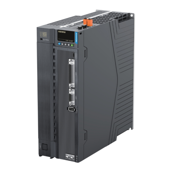
Inovance SV670P Series Installation Manual
Hide thumbs
Also See for SV670P Series:
- Maintenance manual (11 pages) ,
- Troubleshooting manual (104 pages) ,
- Hardware manual (106 pages)
Table of Contents
Advertisement
Quick Links
Advertisement
Table of Contents

Related Manuals for Inovance SV670P Series


Summary of Contents for Inovance SV670P Series
-
Page 2: Preface
Introduction Thank you for purchasing the SV670P series servo drive developed by Inovance. The SV670P series servo drive is a high‑end servo drive designed based on global‑ leading standards and high‑end application needs. It is featured with high speed, high precision, high performance, and tuning‑free Function. - Page 3 Provides instructions on maintenance SV670P Series Servo Drive 19011870 and repair of the equipment. Maintenance Guide Presents the safety function and related SV670P Series Servo Drive Safety certifications and standards, wiring, 19011867 Guide commissioning process, troubleshooting, and functions. Provides information on selection,...
-
Page 4: Table Of Contents
Table of Contents T T a a b b l l e e o o f f C C o o n n t t e e n n t t s s Preface ................1 General Safety Instructions . -
Page 5: General Safety Instructions
Use this equipment according to the designated environment requirements. ● Damage caused by improper use is not covered by warranty. Inovance shall take no responsibility for any personal injuries or property damage ● caused by improper use. Safety Levels and Definitions Indicates that failure to comply with the notice will result in death or severe personal injuries. - Page 6 General Safety Instructions Unpacking Do not install the equipment if you find damage, rust, or signs of use on the equipment ● or accessories upon unpacking. Do not install the equipment if you find water seepage or missing or damaged ●...
- Page 7 General Safety Instructions Handle the equipment with care during transportation and mind your steps to prevent ● personal injuries or equipment damage. When carrying the equipment with bare hands, hold the equipment casing firmly with ● care to prevent parts from falling. Failure to comply may result in personal injuries. Store and transport the equipment based on the storage and transportation ●...
- Page 8 General Safety Instructions Cover the top of the equipment with a piece of cloth or paper during installation. This is ● to prevent unwanted objects such as metal chippings, oil, and water from falling into the equipment and causing faults. After installation, remove the cloth or paper on the top of the equipment to prevent over‑temperature caused by poor ventilation due to blocked ventilation holes.
- Page 9 General Safety Instructions Before power‑on, check that the equipment is installed properly with reliable wiring and ● the motor can be restarted. Check that the power supply meets equipment requirements before power‑on to ● prevent equipment damage or a fire. After power‑on, do not open the cabinet door or protective cover of the equipment, ●...
- Page 10 General Safety Instructions Perform routine and periodic inspection and maintenance on the equipment according ● to maintenance requirements and keep a maintenance record. Repair Equipment installation, wiring, maintenance, inspection, or parts replacement must be ● performed only by professionals. Do not repair the equipment with power ON. Failure to comply will result in an electric ●...
- Page 11 General Safety Instructions Dynamic braking is common in rotating mechanical structures. For example, when ● a motor has stopped running, it keeps rotating due to the inertia of its load. In this case, this motor is in the regenerative state and short‑circuit current passes through the dynamic brake.
-
Page 12: Precautions
Precautions Precautions Observe the installation direction described in this guide. Failure to comply may ● result in equipment fault or damage. Do not install or operate damaged or defective equipment. Failure to comply will ● result in physical injury. Do not install the equipment in environments exposed to water splashes or ●... -
Page 13: Installation Flow Chart
Installation Flow Chart Installation Flow Chart Figure 2‑1 Installation Flow Chart Note The illustration presents the recommended installation procedure. You can adjust the pro‑ cedure as appropriate. ‑ ‑... -
Page 14: Preparation
Derating is required for altitudes above 1000 m (derate 1% for Altitude ● every additional 100 m). For altitudes above 2000 m, contact Inovance. ● Mounting/Operating temperature: 0℃ to +55℃ For temperatures ● between 0℃ to 45℃, derating is not required. For temperatures above 45℃, derate 2% for every additional 1℃. -
Page 15: Installation Clearance
Preparation Requirement Item IP rating IP20. Pollution Degree 2 and below Install the servo drive in a place that meets the following requirements: Free from direct sunlight, dust, corrosive gas, explosive and ● inflammable gas, oil mist, vapor, water drop, and salty element Insusceptible to vibration (away from equipment that may ●... - Page 16 Preparation Figure 3‑2 Clearance for side‑by‑side installation Servo drives rated at 0.2 kW to 0.4 kW support compact installation, in which a clearance of at least 1 mm (0.04 in.) must be reserved between every two servo drives. .When adopting compact installation, derate the load rate to 75%. Figure 3‑3 Clearance for compact installation Servo drives rated at 0.75 kW to 7.5 kW support zero‑clearance installation between every two servo drives, without the need for derating.
-
Page 17: Installation Dimensions
Preparation Figure 3‑4 Zero‑clearance installation Installation Dimensions Servo Drives in Size A (Rated Power: 0.2 kW to 0.4 kW): SV670PS1R6I, SV670PS2R8I Figure 3‑5 Dimension drawing of servo drives in size A Fixing screws: 2–M4; recommended tightening torque: 1.2 N·m Weigh: 0.96 kg ‑... - Page 18 Preparation Servo Drives in Size C (Rated Power: 0.75 kW to 1.5 kW): SV670PS5R5I, SV670PS7R6I, SV670PT3R5I, SV670PT5R4I Figure 3‑6 Dimension drawing of servo drives in size C Fixing screws: 2–M4; recommended tightening torque: 1.2 N·m Weigh: 1.3 kg Servo Drives in Size D (Rated Power: 1.5 kW to 3.0 kW): SV670PS012I, SV670PT8R4I, SV670PT012I Figure 3‑7 Dimension drawing of servo drives in size D Fixing screws: 3–M4;...
-
Page 19: Optional Parts
Preparation Servo Drives in Size E (Rated Power: 2.0 kW to 7.5 kW): SV670PS018I, SV670PS022I, SV670PS027I, SV670PT017I, SV670PT021I, SV670PT026I Figure 3‑8 Dimension drawing of servo drives in size E Fixing screws: 4–M4; recommended tightening torque: 1.2 N·m Weigh: 3.6 kg Optional Parts Fuse and circuit breaker To prevent electric shock, when the fuse is blown or the circuit breaker trips, wait for at... -
Page 20: Cable Preparation
For detailed cable specifications, see the hardware guide. If you have special requirements on the cables, contact Inovance. Crimping The following figure illustrates how to crimp a cable. The crimping method may vary with different cable types. - Page 21 Preparation Figure 3‑10 Crimping a cable ‑ ‑...
-
Page 22: Unpacking Inspection
" Figure 4–1 " on page 21 Check whether the product delivered is in good condition. If Check whether the there is any missing or damage, contact Inovance or your product is intact. supplier immediately. Table 4–1 Dimensions of the outer packing box... - Page 23 If you need to purchase the terminal accessory package separately, please contact Inovance. For the material code of the accessory package for each model, refer to " Table 4–3 " on page 22 Table 4–3 Material code of the accessory package for each model...
-
Page 24: 机械安装
机械安装 机械安装 Safety Cautions Table 5–1 Installation Precautions Description Item Install the servo drive vertically and upward to facilitate heat ● dissipation. For installation of multiple servo drives inside the cabinet, install them side by side. For dual‑row installation, install an air guide plate. Make sure the servo drive is installed vertically to the wall. -
Page 25: Pre-Inspection
机械安装 Description Item As shown in the figure below, route the servo drive cables downwards to prevent liquid from flowing into the servo drive along the cables. Wiring Requirements Insert the dust‑proof cover into the communication port (CN3/ CN4) not in use. This is to prevent unwanted objects, such as solids or liquids, from falling into the servo drive and resulting in faults. -
Page 26: Installing The Absolute Encoder Battery
机械安装 Description All screws are in position and tightened. □ The signal terminal is free from fracture, foreign objects and bent □ pins. Installing the Absolute Encoder Battery The optional S6‑C4A battery box contains the following items: One plastic case. ●... -
Page 27: Mounting The Drive
机械安装 Improper use of the battery may result in liquid leakage which corrodes the components or leads to battery explosion. Observe the following precautions during use: Insert the battery with polarity (+/‑) placed correctly. ● Leaving an idled or retired battery inside the device may lead to electrolyte ●... -
Page 28: Installing The Motor
机械安装 Figure 5‑2 Backplate mounting Note Servo drives in sizes A and C are secured by two screws, with one screw on the top ● and the other one at the bottom. Servo drives in size D are secured by three screws, with two screws on the top and ●... - Page 29 机械安装 The motor can be horizontally or vertically mounted. When it is mounted in direction Note the permissible axial force of the motor (gravity of the drive unit) and the IP ● rating requirement. If a oil seal is used, oil may enter the motor. ●...
- Page 30 机械安装 To prevent excessive wear of the oil seal, leave a small amount of oil on the lip for ● lubrication. The motor can only be installed on a flat, vibration‑free and distortion‑resistant ● support flange surface according to the specified structure. Use hexagon socket screws with strength grade of at least 8.8.
- Page 31 机械安装 brake may be closed again. The voltage drop on the cable should be considered for long‑distance brake cables. The approximate calculation of voltage drop Δ U of a copper cable is as follows: Δ U [V] = 0.042 Ω · mm /m (L/q) ∙...
-
Page 32: Post-Inspection
机械安装 Select the appropriate belt according to the allowable radial load of the servo ● motor and the output power of the motor. When installing the belt, ensure that its tension is lower than the specified ● allowable radial load. See the instructions of the belt manufacturer for detailed installation precautions. -
Page 33: 电气安装
电气安装 电气安装 Safety Cautions Observe the following requirements during wiring of the power supply and main ● circuit: When the main circuit terminal is a connector, remove the connector from the ■ servo drive before wiring. Insert one cable into one cable terminal of the connector. Do not insert ■... - Page 34 电气安装 Figure 6‑1 Main circuit wiring Note 1KM: Electromagnetic contactor; 1Ry: Relay; 1D: Flywheel diode ● DO is set as alarm output (ALM+/‑). When the servo drive alarms, the power supply ● will be cut off automatically. S1R6 and S2R8 are not configured with built‑in regenerative resistors, if the regenerative resistor is needed, connect an external regenerative resistor between P⊕...
- Page 35 电气安装 Figure 6‑2 Main circuit wiring Note 1KM: Electromagnetic contactor; 1Ry: Relay; 1D: Flywheel diode ● The DO is set as alarm output (ALM+/‑). When the servo drive alarms, the power ● supply is cut off automatically and the alarm indicator lights up. Three‑phase 380 V models: SV670PT3R5I, SV670PT5R4I, SV670PT8R4I, ●...
- Page 36 电气安装 Figure 6‑3 Main circuit wiring Note 1KM: Electromagnetic contactor; 1Ry: Relay; 1D: Flywheel diode ● The DO is set as alarm output (ALM+/‑). When the servo drive alarms, the power ● supply is cut off automatically and the alarm indicator lights up. ‑35‑...
-
Page 37: Wiring With The Motor
电气安装 Wiring with the Motor Figure 6‑4 Wiring between the servo drive and terminal‑type motor To avoid flying start, ensure that the phase sequence is correct. Table 6–1 Description of the power cable connector (motor side) for terminal‑type motors Terminal Pin Layout Outline Drawing of the Flange Size Signal Name... - Page 38 ● Power cable colors are subject to the actual product. All cable colors mentioned in ● this guide refer to Inovance cable colors. Table 6–2 Description of the pass‑through power cable connector (motor side) Terminal Pin Layout Outline Drawing of the...
-
Page 39: Post-Inspection
[1] The flange size refers to the width of the mounting flange. ● Power cable colors are subject to the actual product. All cable colors mentioned in ● this guide refer to Inovance cable colors. Post-Inspection Table 6–5 Inspection Checklist Description The power input terminals (L1C, L2C, L1, L2, L3, R, S, T) of the □... - Page 40 *19011868A01*...
Need help?
Do you have a question about the SV670P Series and is the answer not in the manual?
Questions and answers