Advertisement
Available languages
Available languages
Quick Links
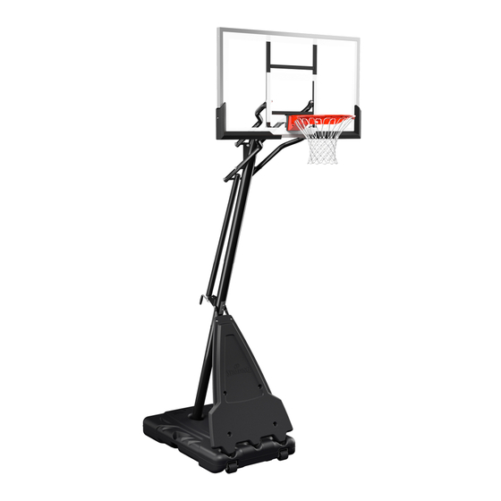
PORTABLE BASKETBALL SYSTEM
Toll-Free Customer Service Number
U.S.:
1-800-558-5234
Canada:
1-800-284-8339
Europe:
+353 51 379777
Australia: 1300 367 582
www.spalding.com
WARNING
READ AND UNDERSTAND THE OPERATOR'S
MANUAL BEFORE USING THIS UNIT.
FAILURE TO FOLLOW THE OPERATING
INSTRUCTIONS COULD RESULT IN INJURY
OR DAMAGE TO PROPERTY.
Owner's Manual
Model Number:
(found on product box)
02/22 ID#
M686B22
Advertisement
Chapters

Subscribe to Our Youtube Channel
Related Manuals for SPALDING BC0105


Summary of Contents for SPALDING BC0105
- Page 1 Toll-Free Customer Service Number U.S.: 1-800-558-5234 Canada: 1-800-284-8339 Europe: +353 51 379777 Australia: 1300 367 582 www.spalding.com WARNING READ AND UNDERSTAND THE OPERATOR’S MANUAL BEFORE USING THIS UNIT. FAILURE TO FOLLOW THE OPERATING INSTRUCTIONS COULD RESULT IN INJURY OR DAMAGE TO PROPERTY. M686B22...
-
Page 2: Table Of Contents
FAILURE TO FOLLOW OPERATING INSTRUCTIONS COULD RESULT IN INJURY OR PROPERTY DAMAGE. Contact Questions or missing parts? Do NOT go back to the store! Email: warrantyservice@custserv.fotlinc.com Customer Service 1-800-558-5234 Toll-Free Number: Mailing Address: Spalding PO Box 90015 Bowling Green, KY 42102... -
Page 3: Warranty
Warranty Warranty For the very latest Basketball System Warranty information, please visit www.Spalding.com or call Spalding Customer Service at 1-800-558-5234. Safety Information WARNING FAILURE TO FOLLOW THESE SAFETY INSTRUCTIONS MAY RESULT IN SERIOUS INJURY OR PROPERTY DAMAGE AND WILL VOID THE WARRANTY. -
Page 4: Test-Fit Close Tolerance Bolts
Test-Fit Close Tolerance Bolts Test-Fit Close Tolerance Bolts To ensure optimal playability of the backboard system, a close tolerance fit between the elevator components and hardware is required. Test-fit large bolts into large holes of elevator tubes, backboard brackets, and triangle plates. Carefully rock them in a circular motion to remove any excess paint from holes, if necessary. - Page 5 Package Contents KIT 1 – BASE ASSEMBLY – 209131 13 Pushnut (x2) 18 Bolt, Hex Head, 5/16-18 x 0.75 L (x4) 24 Washer, Flat, 5/16 (x4) 203153 hex head bolt 5/16 x 3/4 KIT 2 – POLE TO BASE ASSEMBLY – 209132 203099Hex Locknut (Nylon Insert) 5/16-18 203153 hex head bolt 5/16 x 3/4 203100...
- Page 6 Package Contents ELEVATOR ASSEMBLY Bracket, Pole Mount (x1) 27 Pin, Handle (x1) 17 Sleeve, Screw Jack (x1) 51 Cap, Screw Jack (x1) 52 Handle, Screw-Jack (x1) 55 Screw Jack (x1) KIT 3 – ELEVATOR TO POLE ASSEMBLY – 210502 203099Hex Locknut (Nylon Insert) 5/16-18 203100 NUT, HEX FLANGE, 5/16-18 10 Nut, Ny-lock, 5/16-18 (x1)
- Page 7 Package Contents BACKBOARD ASSEMBLY 11 Bolt, Hex, 1/2-13x4 Long (x1) 29 Bolt, Hex Head, 1/2-13 x 10.25 L (x3) 32 Elevator Tube, Lower, Long (x2) 35 Elevator Tube, Upper, Short (x2) 38 Cap, Pole Top (x1) 40 Triangle Plates (x2) 54 Backboard (x1) 56 Board Pad, Left Section (x1) 57 Board Pad, Right Section (x1)
-
Page 8: Goal Assembly
Package Contents KIT 5 – BACKBOARD – 210504 PN 205679 BOLT,HEX HD 1/2-13 X 2", 1.5”TH 23 Bolt, Hex Head, 1/2-13 x 2 Long (x4) 30 Spacer, Plastic, 0.50 I.D. x 0.13 Long (x4) 31 Lock Nut, Hex 1/2-13 (x8) Spacer, 0.5 ID x 0.98 OD x 1.64 36 Spacer, Plastic, 0.53 ID x 2.38 L (x2) 49 Spacer, 0.53 ID x 0.75 OD x 3.25 L (x1) L (x4) -
Page 9: Tools & Materials For Assembly
Tools & Materials for Assembly KIT 6 – GOAL – 208877 37 Washer, Flat, 0.625 I.D. x .1.5 O.D. (x1) 39 Screw, #10-0.394" Long (x2) 46 Bracket, Reinforcement, Slam Jam (x1) 47 Spring, Rim (x1) 48 Nut, Special, 3/8-16 (x1) Tools &... -
Page 10: Assembly Overview
Assembly Overview Assembly Overview Backboard (Section E, F ) Elevator System (Section D, E, F, G) Top Pole (Section B) Bottom Pole Rim (Section H) (Section B) Stadium Pad (Section C) Middle Pole (Section B) Struts (Section C) Base (Section A) Wheel Carriage (Section A) -
Page 11: Assemble The Base
Assemble the Base Assemble the Base Required Parts: Completed Base Assembly: • Kit 1 • Kit 2 • Scrap Wood Board • Socket Wrench or Wrench • Mallet ASSEMBLE THE WHEELS 1. Insert the wheels (8) into the wheel brackets (7). 2. - Page 12 Assemble the Base ASSEMBLE THE WHEELS 3. Secure the wheel brackets (7) and wheel assembly to the base (1) with the bolts (18) and washers (24). ASSEMBLE THE OVAL POLE 1. Identify the top (6), middle (5), and 3 1/2" bottom (4) oval pole sections.
- Page 13 WHEN PROPERLY POUNDED TOGETHER, THE POLE SECTIONS SHOULD HAVE A 3 1/2" (9 CM) OVERLAP. IF MINIMUM POLE ENGAGEMENT OVERLAP OF 3 1/2" (9 CM) CANNOT BE ACHIEVED !! STOP !! DO NOT PROCEED TO THE NEXT STEP! - CALL SPALDING CUSTOMER SERVICE AT 1-800-558-5234 FOR ASSISTANCE.
- Page 14 Assemble the Base ASSEMBLE THE OVAL POLE 5. Align the assembled oval pole section with the bottom (6) pole section and slide together. 6. Bounce the assembled sections on a scrap wood board until the overlap reaches the marked line. 3 1/2"...
- Page 15 Assemble the Base INSTALL THE POLE ONTO THE BASE 1. Attach the pole assembly to the base (1) using the bolts (25) and the pole mounting plate (19). WARNING TWO PEOPLE ARE REQUIRED FOR THIS PROCEDURE . FAILURE TO FOLLOW THIS WARNING COULD RESULT IN SERIOUS INJURY AND/OR PROPERTY DAMAGE .
- Page 16 Assemble the Base INSTALL THE POLE ONTO THE BASE 3. Rotate the non-secured ends of the base struts (2) to align with the mounting holes in the base (1). 4. Secure the ends of the base struts (2) to the base frame using bolts (18) and lock washers (24).
-
Page 17: Elevator Assembly
Elevator Assembly Elevator Assembly Required Parts: Completed Elevator Assembly: • Kit 3 • Socket Wrench or Wrench INSTALL THE ELEVATOR ASSEMBLY 1. Securely rest the assembly on a sawhorse. 2. Slide the screw-jack sleeve (17) over the screw jack assembly (55) and attach the cap (51) to the top end. - Page 18 Elevator Assembly INSTALL THE ELEVATOR ASSEMBLY 3. Install the pole mount bracket (15) and the reinforcement bracket (42) to the middle pole (5) using the carriage bolts (16) and flange nuts (14). 4. Tighten the flange nuts (14) completely. 5. Attach the screw-jack sleeve (17) to the pole bracket (15) using bolt (20) and nut (10).
- Page 19 Elevator Assembly INSTALL THE ELEVATOR ASSEMBLY 6. Attach the handle (52) to the screw jack with the pin (27).
-
Page 20: Assemble The Upper Elevator
Assemble the Upper Elevator Assemble the Upper Elevator Required Parts: Completed Backboard Assembly: • Kit 4 • Kit 5 • Wrenches and/or Socket Wrenches • Socket Wrench Extension • Phillips Screwdriver • Sawhorse WARNING TWO PEOPLE ARE REQUIRED FOR THIS PROCEDURE. FAILURE TO FOLLOW THIS WARNING COULD RESULT IN SERIOUS INJURY AND/OR PROPERTY DAMAGE. - Page 21 Assemble the Upper Elevator ATTACH THE ELEVATOR TUBE ASSEMBLY 2. While the system is securely resting on the sawhorse. Install elevator tubes (32 and 35) to top pole section (4). Install pole cap (38) at this time. WARNING TIGHTEN THE BOLTS (A5) IN THE LOCK NUTS (A2) UNTIL FLUSH (EVEN) WITH THE LOCK NUT’S OUTER EDGE. NOTE TEST-FIT THE LARGE BOLTS INTO THE LARGE HOLES OF THE ELEVATOR TUBES, BACKBOARD BRACKETS, AND TRIANGLE PLATES.
- Page 22 Assemble the Upper Elevator ATTACH THE BACKBOARD 1. While still supported on sawhorse, attach the elevator tubes (32, 35) to the backboard using the spacers (30), bolts (23), and nuts (31). 2. Insert the t-bolt (45) into the slam jam bracket (44) and attach to board using the bolts (26) and nuts (14).
- Page 23 Assemble the Upper Elevator ATTACH THE ELEVATOR ASSEMBLY 1. Attach the handle assembly (55) to the lower elevator tubes (32) using the bolt (29), spacers (36), and nut (31).
-
Page 24: Assemble The Goal
Assemble the Goal Assemble the Goal Required Parts: Completed Goal Assembly: • Kit 6 • Wrenches and/or Socket Wrenches • Socket Wrench Extension • Phillips Screwdriver ASSEMBLE THE GOAL 1. Fit the rim (34) securely into the slam jam bracket (44). Allow the t-bolt (45) to slip through the center hole in the rim (34). - Page 25 Assemble the Goal ASSEMBLE THE GOAL 2. Install the reinforcement bracket (46) onto the t-bolt (45). 3. Install the spring (47) onto the t-bolt (45).
- Page 26 Assemble the Goal ASSEMBLE THE GOAL 4. Install the special nut (48) and washer (37) onto the t bolt (45). 5. Tighten the nut (48) until 1/8" of the bolt threads onto the exposed end of the t-bolt 1/8" (45). (3mm)
- Page 27 Assemble the Goal ASSEMBLE THE GOAL 6. Install the rim cover using the cover screws. 7. Thread the net (43) onto the rim (34).
- Page 28 Assemble the Goal ASSEMBLE THE GOAL 8. Apply the Height Adjustment and Moving Label (33) to the front of the pole, where it is clearly visible. HEIGHT ADJUSTMENT Rotate crank handle to raise and lower backboard. Do not over crank handle beyond the manufactured height indicator range of 7-1/2 - 10 feet.
- Page 29 Assemble the Goal ASSEMBLE THE GOAL 13. Rotate the crank handle to move the backboard up or down to the desired height. WARNING DO NOT ALLOW CHILDREN TO ADJUST THE HEIGHT. DO NOT OVER CRANK THE HANDLE BEYOND THE HEIGHT INDICATOR RANGE OF 7-1/2 TO 10 FEET OR THE ADJUSTMENT MECHANISM MAY BE DAMAGED.
-
Page 30: Fill The Assembled Unit For Use
Fill The Assembled Unit For Use Fill The Assembled Unit For Use Required Parts: Complete Unit Assembly: • Water • Sand WARNING • TWO CAPABLE ADULTS ARE REQUIRED FOR THIS PROCEDURE. FAILURE TO FOLLOW THIS WARNING COULD RESULT IN SERIOUS INJURY. •... - Page 31 Fill The Assembled Unit For Use INSTALL THE COVER 1. Roll completed assembly to desired position. Fill the base with water (approx. 40 gallons (151 Liters)) or sand (475 lbs. (216 kg)) and place the cap (41) into base (1).
-
Page 32: Operation
Operation Operation ADJUSTING THE HEIGHT 1. Rotate the crank handle to move the backboard up or down to the desired height. WARNING DO NOT ALLOW CHILDREN TO ADJUST THE HEIGHT. DO NOT OVER CRANK THE HANDLE BEYOND THE HEIGHT INDICATOR RANGE OF 7-1/2 TO 10 FEET OR THE ADJUSTMENT MECHANISM MAY BE DAMAGED. -
Page 33: Parts List
Parts List Parts List... - Page 34 Parts List Item Part No . Description Item Part No . Description 600262 Base 202528 Pin, Actuator Assembly 908556 Strut, Pole to Base 901967 Cover Plate, Rim Bolt, Hex Head, 1/2-13 x 10.25 205355 Drill Bit, 11/64 205809 Long Spacer, Plastic, 0.50 I.D. x 0.13 901789 Top Pole, Black 208251...
- Page 35 Parts List Item Part No . Description Item Part No . Description 700009 Handle, Elevator Assembly 20157901 Board Pad, Right Section 204872 Label, Height Indicator 206303 Washer, Flat, 1/4 Backboard, Acrylic 201538 Screw, 1/4 x 1.00” Long 80034403 Screw-Jack Assembly 202219 Protector, Screw 20157801...
-
Page 36: Safety Labels
PROPERTY DAMAGE. of 7-1/2 - 10 feet. 1.800.558.5234 | www.hu ysports.com Owner must ensure that all players know and follow these rules www.spalding.com for safe operation of the system. Damage may be caused to the WARNING LABELS AND INSTRUCTIONS MUST ACCOMPANY screw jack’s internal adjustment... -
Page 37: Manual Del Propietario
EE. UU.: 1-800-558-5234 Canadá: 1-800-284-8339 Europa: +353 51 379777 Australia: 1300 367 582 www.spalding.com ADVERTENCIA LEA Y COMPRENDA EL MANUAL DEL OPERADOR ANTES DE USAR ESTA UNIDAD. EL INCUMPLIMIENTO DE LAS INSTRUCCIONES DE FUNCIONAMIENTO PODRÍA OCASIONAR LESIONES O DAÑOS MATERIALES. -
Page 38: Call Toll-Free Customer Service
EL INCUMPLIMIENTO DE LAS INSTRUCCIONES DE FUNCIONAMIENTO PODRÍA OCASIONAR LESIONES O DAÑOS MATERIALES. Contacto ¿Tiene preguntas o le falta alguna pieza? ¡NO vuelva a la tienda! Correo electrónico: warrantyservice@custserv.fotlinc.com Teléfono gratuito del 1-800-558-5234 servicio al cliente: Dirección postal: Spalding PO Box 90015 Bowling Green, KY 42102... -
Page 39: Garantía
Garantía Garantía Para obtener la información más reciente sobre la Garantía del Sistema de Baloncesto, visite www.Spalding.com o llame al Servicio al Cliente de Spalding al 1-800-558-5234. Información de seguridad ADVERTENCIA EL INCUMPLIMIENTO DE ESTAS INSTRUCCIONES DE SEGURIDAD PUEDE OCASIONAR LESIONES GRAVES O DAÑOS MATERIALES Y ANULARÁ... -
Page 40: Comprobación Del Ajuste De Los Pernos De Tolerancia Estrecha
Comprobación del ajuste de los pernos de tolerancia estrecha Comprobación del ajuste de los pernos de tolerancia estrecha Para garantizar que el sistema del tablero ofrece una calidad de juego óptima, se requiere una estrecha tolerancia del ajuste entre los componentes del elevador y los herrajes. Compruebe el ajuste de los pernos grandes en los orificios grandes de los tubos del elevador, los soportes del tablero y las placas triangulares. - Page 41 Contenido del paquete KIT 1 – MONTAJE DE LA BASE – 209131 Perno, cabeza hexagonal, 13 Tuerca dentada (x2) 24 Arandela, plana, 5/16 (x4) 203153 hex head bolt 5/16 x 3/4 5/16-18 x 0.75 de largo (x4) KIT 2 – MONTAJE DEL POSTE EN LA BASE – 209132 Núm .
- Page 42 Contenido del paquete MONTAJE DEL ELEVADOR Núm . 17 Núm . 51 Núm . 15 Núm . 55 Núm . 27 Núm . 52 Soporte, montaje del poste (x1) 27 Pasador, manivela (x1) 17 Funda, elevador mecánico (x1) 51 Tapón, elevador mecánico (x1) 52 Manivela, elevador mecánico (x1) 55 Elevador mecánico (x1) KIT 3 –...
- Page 43 Contenido del paquete MONTAJE DEL TABLERO Núm . 11 Núm . 29 Núm . 32 Núm . 38 Núm . 54 Núm . 35 Núm . 40 Núm . 57 Núm . 56 Perno, hexagonal, 1/2-13 x 4 de Perno, cabeza hexagonal, 1/2-13 Tubo del elevador, inferior, largo largo (x1) x 10.25 de largo (x3)
- Page 44 Contenido del paquete KIT 5 – TABLERO – 210504 Núm . 30 Núm . 31 Núm . 23 PN 205679 BOLT,HEX HD 1/2-13 X 2", 1.5”T Núm . 36 Núm . 50 Núm . 49 Perno, cabeza hexagonal, Espaciador, de plástico, 0.50 d. int. Tuerca, Nylock, hexagonal 1/2-13 x 2 de largo (x4) x 0.13 de largo (x4)
- Page 45 Contenido del paquete MONTAJE DE LA CANASTA Núm . 34 Núm . 28 Núm . 44 AJUSTE DE LA ALTURA Gire la manivela para subir o bajar el tablero. No gire demasiado la manivela de modo que el tablero quede fuera del rango de altura de fábrica de 7-1/2 pies a 10 pies (2.3 m a 3.05 m).
-
Page 46: Herramientas Y Materiales Para El Montaje
Herramientas y materiales para el montaje Herramientas y materiales para el montaje Gafas de Llave de vaso Extensión de llave Llave 2 adultos capaces Mazo seguridad 1/2", 9/16", 3/4" de vaso 1/2", 9/16", 3/4" (OPCIONAL) Destornillador Escalera de Tabla de madera Manguera de Cinta métrica Caballete... -
Page 47: Resumen Del Montaje
Resumen del montaje Resumen del montaje Tablero (Secciones E, F) Sistema elevador (Secciones D, E, F, G) Poste superior (Sección B) Poste inferior Aro (Sección H) (Sección B) Cubierta estilo cancha (Sección C) Poste intermedio (Sección B) Puntales (Sección C) Base (Sección A) Soporte con ruedas (Sección A) -
Page 48: Montaje De La Base
Montaje de la base Montaje de la base Piezas necesarias: Montaje completo de la base: • Kit 1 • Kit 2 • Tabla de madera de desecho • Llave de vaso o llave • Mazo MONTAJE DE LAS RUEDAS 1. Introduzca las ruedas (8) en los soportes de las ruedas (7). 2. -
Page 49: Montaje De Las Ruedas
Montaje de la base MONTAJE DE LAS RUEDAS 3. Fije los soportes de las ruedas (7) y el montaje de las ruedas a la base (1) con los pernos (18) y las arandelas (24). Núm . 18 Núm . 24 Núm . - Page 50 TENER UNA SUPERPOSICIÓN DE 3 1/2" (9 CM). SI NO PUEDE CONSEGUIR UNA SUPERPOSICIÓN DE ENGANCHE DE 3 1/2” (9 CM), ¡¡PARE!! ¡NO CONTINÚE CON EL SIGUIENTE PASO! - LLAME AL SERVICIO AL CLIENTE DE SPALDING AL 1-800-558-5234 PARA RECIBIR AYUDA.
- Page 51 Montaje de la base MONTAJE DEL POSTE OVALADO 5. Alinee la sección del poste ovalado montada con la sección inferior del poste (6) y encájelas. 6. Empuje las secciones ensambladas sobre el bloque de madera hasta que la superposición alcance la línea marcada. Núm .
- Page 52 Montaje de la base COLOCACIÓN DEL POSTE EN LA BASE 1. Fije el conjunto del poste a la base (1) con los pernos (25) y la placa de montaje del poste (19). ADVERTENCIA SE REQUIEREN DOS PERSONAS PARA ESTE PROCEDIMIENTO . EL INCUMPLIMIENTO DE ESTA ADVERTENCIA Núm .
- Page 53 Montaje de la base COLOCACIÓN DEL POSTE EN LA BASE 3. Gire los extremos no fijados de los puntales de la base (2) para alinearlos con los orificios de montaje de la base (1). 4. Fije los extremos de los puntales de Núm .
-
Page 54: Montaje Del Elevador
Montaje del elevador Montaje del elevador Piezas necesarias: Montaje completo del elevador: • Kit 3 • Llave de vaso o llave COLOCACIÓN DEL MONTAJE DEL ELEVADOR 1. Apoye el montaje de forma segura en el caballete. 2. Deslice la funda del elevador mecánico (17) por encima del elevador mecánico (55) y coloque la tapa (51) en el extremo superior. - Page 55 Montaje del elevador COLOCACIÓN DEL MONTAJE DEL ELEVADOR 3. Instale el soporte del montaje del poste (15) Núm . 14 y el soporte de refuerzo (42) en el poste intermedio (5) utilizando los pernos de carruaje (16) y las tuercas bridadas (14). 4.
- Page 56 Montaje del elevador COLOCACIÓN DEL MONTAJE DEL ELEVADOR 6. Fije la manivela (52) en el elevador mecánico con el pasador (27). Núm . 27 Núm . 52...
-
Page 57: Montaje Del Elevador Superior
Montaje del elevador superior Montaje del elevador superior Piezas necesarias: Montaje completo del tablero: • Kit 4 • Kit 5 • Llaves y/o llaves de vaso • Extensión de llave de vaso • Destornillador de estrella • Caballete ADVERTENCIA SE REQUIEREN DOS PERSONAS PARA ESTE PROCEDIMIENTO. EL INCUMPLIMIENTO DE ESTA ADVERTENCIA PODRÍA OCASIONAR LESIONES GRAVES Y/O DAÑOS MATERIALES. - Page 58 Montaje del elevador superior COLOCACIÓN DEL MONTAJE DEL TUBO ELEVADOR 2. Mientras el sistema está apoyado de forma segura en el caballete. Coloque los tubos del elevador (32 y 35) en la sección del poste superior (4). En este momento, coloque la tapa del poste (38). ADVERTENCIA APRIETE LOS PERNOS (A5) EN LAS CONTRATUERCAS (A2) HASTA QUEDAR PAREJOS CON EL BORDE EXTERIOR DE LA CONTRATUERCA.
- Page 59 Montaje del elevador superior COLOCACIÓN DEL TABLERO 1. Mientras se encuentra apoyado en el caballete, coloque los tubos del elevador (32, 35) al tablero utilizando los espaciadores (30), los pernos (23) y las tuercas (31). Núm . 31 Núm . 30 Núm .
- Page 60 Montaje del elevador superior COLOCACIÓN DEL MONTAJE DEL ELEVADOR 1. Fije el montaje de la manija (55) en los tubos del elevador inferiores (32) utilizando el perno (29), los espaciadores (36) y la tuerca (31). Núm . 29 Núm . 32 Núm .
-
Page 61: Montaje De La Canasta
Montaje de la canasta Montaje de la canasta Piezas necesarias: Montaje completo de la canasta: • Kit 6 • Llaves y/o llaves de vaso • Extensión de llave de vaso • Destornillador de estrella MONTAJE DE LA CANASTA 1. Fije firmemente el aro (34) en el soporte slam jam (44). - Page 62 Montaje de la canasta MONTAJE DE LA CANASTA 2. Instale el soporte de refuerzo (46) en el perno en T (45). Núm . 46 Núm . 45 3. Coloque el resorte (47) en el perno en T (45). Núm . 47 Núm .
- Page 63 Montaje de la canasta MONTAJE DE LA CANASTA 4. Coloque la tuerca especial (48) y la arandela (37) en el perno en T (45). Núm . 37 Núm . 48 Núm . 45 5. Apriete la tuerca (48) hasta 1/8" (3 mm) de las roscas del perno en el extremo expuesto 1/8"...
- Page 64 Montaje de la canasta MONTAJE DE LA CANASTA 6. Coloque la cubierta del aro utilizando los tornillos de la cubierta. Núm . 34 Núm . 39 Núm . 28 7. Enganche la red (43) en el aro (34). Núm . 43 Núm .
- Page 65 Montaje de la canasta MONTAJE DE LA CANASTA 8. Ponga la etiqueta de ajuste de altura y movimiento (33) en la parte frontal del poste, donde pueda verse de forma clara. Núm . 33 AJUSTE DE LA ALTURA Gire la manivela para subir o bajar el tablero.
- Page 66 Montaje de la canasta MONTAJE DE LA CANASTA 13. Gire la manivela para mover el tablero hacia arriba o hacia abajo hasta que alcance la altura deseada. ADVERTENCIA NO PERMITA QUE LOS NIÑOS AJUSTEN LA ALTURA. NO GIRE DEMASIADO LA MANIVELA DE MODO QUE EL TABLERO QUEDE FUERA DEL RANGO DE ALTURA DE 7-1/2 PIES A 10 PIES (2.3 M A 3.05 M), YA QUE EL MECANISMO DE AJUSTE...
-
Page 67: Llenado De La Unidad Montada Para Su Uso
Llenado de la unidad montada para su uso Llenado de la unidad montada para su uso Piezas necesarias: Montaje completo de la unidad: • Agua • Arena ADVERTENCIA • SE REQUIEREN DOS ADULTOS CAPACES PARA ESTE PROCEDIMIENTO. EL INCUMPLIMIENTO DE ESTA ADVERTENCIA PODRÍA OCASIONAR LESIONES GRAVES Y/O DAÑOS MATERIALES. -
Page 68: Funcionamiento
Funcionamiento Funcionamiento AJUSTE DE LA ALTURA 1. Gire la manivela para mover el tablero hacia arriba o hacia abajo hasta que alcance la altura deseada. ADVERTENCIA NO PERMITA QUE LOS NIÑOS AJUSTEN LA ALTURA. NO GIRE DEMASIADO LA MANIVELA DE MODO QUE EL TABLERO QUEDE FUERA DEL RANGO DE ALTURA DE 7-1/2 PIES A 10 PIES (2.3 M A 3.05 M), YA QUE EL MECANISMO DE AJUSTE PODRÍA DAÑARSE. -
Page 69: Listado De Piezas
Listado de piezas Listado de piezas... - Page 70 Listado de piezas Artículo Cant . Núm . de Descripción Artículo Cant . Núm . de Descripción pieza pieza 600262 Base 202528 Pasador, montaje del activador 908556 Puntal, poste a la base 901967 Placa de cubierta, aro Perno, cabeza hexagonal, 1/2-13 205355 Broca, 11/64 205809...
- Page 71 Listado de piezas Artículo Cant . Núm . de Descripción Artículo Cant . Núm . de Descripción pieza pieza Almohadilla del tablero, sección 700009 Manivela, montaje del elevador 20157901 derecha 204872 Etiqueta, indicadora de altura 206303 Arandela, plana, 1/4 Tablero, acrílico 201538 Tornillo, 1/4 x 1.00”...
-
Page 72: Ajuste De La Altura
Australian only OBSERVE THIS ODILY INJURY AND / French only - board warning MISE EN GARDE : © Copyright 2022 de Russell Brands, LLC www .Spalding .com SONT PAS CONÇUS POUR SUPPORTER UN -RESPECT DE CETTE MISE EN GARDE PEUT...
Need help?
Do you have a question about the BC0105 and is the answer not in the manual?
Questions and answers