Table of Contents
Advertisement
Quick Links
Advertisement
Table of Contents

Related Manuals for Time Electronics 1021


Summary of Contents for Time Electronics 1021
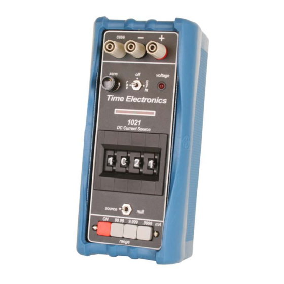
- Page 1 User Manual 1021 Milliamp Source with Null Indicator Version 1.5 11-23 Time Electronics Ltd Unit 5, TON Business Park, 2-8 Morley Road, Tonbridge, Kent, TN9 1RA, United Kingdom. T: +44 (0) 1732 355993 | F: +44 (0) 1732 350198 mail@timeelectronics.co.uk | www.timeelectronics.com...
- Page 2 All rights reserved. Nothing from this manual may be multiplied, or made public in any form or manner, either electronically or hard copy, without prior written consent from Time Electronics Ltd. This also applies to any schematics, drawings and diagrams contained herein.
-
Page 3: Table Of Contents
Time Electronics 1021 Milliamp Source User Manual Contents Introduction ............................ 4 1021 DC Milliamp Source ........................4 Specifications ............................5 Controls ............................6 Operating Instructions ........................7 Preliminaries ............................7 Normal Operation ..........................7 Measurement of Current ........................8 Voltage Compliance Adjustment - V O/P ..................9 Overload Conditions .......................... -
Page 4: Introduction
DC current accurately by using the null facility to back off the unknown current. Resolution of 1 μA is possible. Operation of the 1021 is fast and simple operation. The user needs to only to switch on, check the battery condition, select the range, and set the required current using the thumbwheel switches. -
Page 5: Specifications
Time Electronics 1021 Milliamp Source User Manual Specifications Output: 0 to 99.99 mA in 3 ranges: 0 to 99.99 mA in 10 µA steps 0 to 9.999 mA in 1 µA steps 0 to 999.9 µA in 0.1 µA steps Accuracy: ±... -
Page 6: Controls
On/Off button. Battery Level Indicator Green: Ready for use Red: Change or re-charge batteries. V/OP The 1021 is overload protected and a Re-charge Socket front panel indicator shows when For charging the battery pack. insufficient drive voltage is available. Drive output voltage is adjustable... -
Page 7: Operating Instructions
It is important to understand the voltage capability and the voltage limit indicator of the instrument to ensure that requirements are within limits. Under no circumstances must an additional voltage be connected in series with the output of the 1021 in an attempt to increase the voltage capability as this will cause damage to the output circuitry. -
Page 8: Measurement Of Current
Time Electronics 1021 Milliamp Source User Manual Measurement of Current To measure mA, follow the steps below: 1. Power on the unit. 2. Check the battery level indicator on the top of the unit: Green: Ready for use. Red: Change or recharge batteries. -
Page 9: Voltage Compliance Adjustment - V O/P
10 to 16 hours. The battery charging rate is such that the battery cannot be damaged by overcharging. It is not recommended that the 1021 be operated during battery recharge although output currents of a few milliamps at low compliance voltage can be obtained without discharging the batteries. -
Page 10: Electrical Noise Pick-Up
(several volts peak to peak) the output circuitry of the 1021 is overloaded by the noise signal and it converts it into a DC offset with results in an error in the output. -
Page 11: Common Noise Mode
The standard recharger requires a mains input of 200 V to 240 V at 50/60 Hz. A recharger requiring 100V to 120V at 50/60 Hz is also available but should be specified when ordering. The recharger is connected to the 1021 by a miniature 2 pin plug and socket shaped to ensure correct polarity. -
Page 12: Maintenance And Repair
Fuses are rated at F1A (F1), and F250mA (F2), and have dimensions 20mm length by 5mm diameter. The fuses are available from Time Electronics Ltd or your local supplier. Repair NOTE: No repair work should be undertaken by the customer while the instrument is under warranty as such work may render the warranty invalid. -
Page 13: Recalibration
You should also ensure that the correct equipment is available before attempting recalibration. There are 2 ways the 1021 can be recalibrated: (a) The output current can be converted to a voltage by connecting a precision resistor across the output terminals. -
Page 14: Linearity
The linearity of the output is determined by specially matched resistors mounted on the rear of the digit switches. The matching is done when the 1021 is manufactured. Under normal operating conditions the high performance of these resistors ensures that the 1021 linearity will remain within specification for the instrument’s lifetime. -
Page 15: Warranty And Servicing
Time Electronics’ total liability is limited to repair or replacement of the product. Note that if Time Electronics determine that the fault on a returned product has been caused by the user, we will contact the customer before proceeding with any repair. - Page 16 User Manual Returning Instruments Prior to returning your product please contact Time Electronics. We will issue a return merchandise authorization (RMA) number that is to accompany the goods returning. Further instructions will also be issued prior to shipment. When returning instruments, please ensure that they have been adequately packed, preferably in the original packing supplied.
Need help?
Do you have a question about the 1021 and is the answer not in the manual?
Questions and answers