
Subscribe to Our Youtube Channel
Related Manuals for Renishaw APCA Series


Summary of Contents for Renishaw APCA Series
- Page 1 Installation and user’s guide H-6596-8500-03-A APCA and APCS tool setting probes Original instructions – translation of these original instructions are available on request...
- Page 2 Publications for this product are available by scanning the barcode or visiting www.renishaw.com/apc. Für dieses Produkt stehen weitere Informationen zur Verfügung. Scannen Sie dazu den Barcode oder besuchen Sie www.renishaw.de/apc. Para acceder a las publicaciones sobre este producto escanee el código de barras o visite www.renishaw.es/apc.
- Page 3 Dostęp do dokumentacji tego produktu można uzyskać, skanując kod kreskowy lub odwiedzając witrynę www.renishaw.pl/apc. Publikace pro tento produkt jsou k dispozici po naskenování QR kódu nebo na stránce www.renishaw.cz/apc. Если вас интересует информация об этом продукте, отсканируйте штрих-код или посетите сайт...
- Page 4 This page is intentionally left blank.
-
Page 5: Table Of Contents
Contents Before you begin ......................... v Disclaimer ........................v Trade marks ........................v Warranty ......................... vi China RoHS ........................vi Changes to equipment ....................vi CNC machines ....................... vi Care of the APC ......................vi Equipment operation ...................... vi Patents ........................... vi EU declaration of conformity ..................vii WEEE directive ......................vii REACH regulation ......................vii... - Page 6 Contents (continued) Interface unit ........................3 Introduction ........................3 Installing the interface unit ....................4 Specification ........................5 Dimensions .......................... 7 Preparing the machine for APC installation ..............8 Introduction ........................8 Machine cutout (orientation to suit installation) ............... 8 Acceptable orientation of the APC ..................
- Page 7 Contents (continued) Mechanical protection ....................15 Air blast stalk ......................... 15 APCA with “air bleed” (circuit 1) ..................16 Operation sequence (circuit 1) ..................17 APCA with “air bleed” (circuit 2) ..................18 Operation sequence (circuit 2) ..................19 APCS with “air bleed” (circuit 3) ..................20 Operation sequence (circuit 3) ..................
- Page 8 Contents (continued) Service and Maintenance ....................30 Service .......................... 30 Maintenance ......................... 30 Cleaning instructions ..................... 31 Fault-finding ........................32 Parts list ..........................34...
-
Page 9: Before You Begin
The publication of material within this document does not Renishaw plc or its subsidiaries. imply freedom from the patent rights of Renishaw plc. All other brand names and product names used in this document are trade names, trade marks, or registered trade marks of their respective owners. -
Page 10: Warranty
Unless otherwise specifically agreed in writing between you and Renishaw, if you purchased the equipment from Care of the APC a Renishaw company, the warranty provisions contained Keep system components clean (for more information in Renishaw’s CONDITIONS OF SALE apply. -
Page 11: Eu Declaration Of Conformity
The user is cautioned that any changes or modifications, reuse or recycling. Correct disposal of this product not expressly approved by Renishaw plc or authorised will help to save valuable resources and prevent representative, could void the user’s authority to operate potential negative effects on the environment. -
Page 12: Safety
Operation in operation, including those mentioned in Renishaw of this equipment in a residential area is likely to cause product documentation, and to ensure that adequate harmful interference, in which case you will be required to guards and safety interlocks are provided. -
Page 13: Warnings
+86 21 6180 6416 • Sound pressure level: this device emits noise as +86 21 6180 6418 an essential part of its operation and has been shanghai@renishaw.com measured at 76 dB(A). www.renishaw.com.cn • Pinch point: when this device operates there is a pinching hazard between the stylus cube and the 安全须知... - Page 14 Before you begin (continued) 机床供应商/安装商须知 自动测针保护罩 (APC) 系统必须由有资质的人员在遵守 相关安全措施的前提下进行安装。在开始工作之前,须确 保机床电源关闭,处于安全状态,并且HSI或HSI-C的电 源已断开。 警告 集成商必须将该设备的以下残余风险控制在可接受范围 内: • • 声压级:该设备运行时的一个基本特点是发出噪声, 噪声值为76 dB(A)。 • • 注意卷夹:当设备运行时,在方形测针和保护罩之间 存在夹伤危险。 • • 在机床内安装或清洁该产品时,必须谨慎操作以确保 避开尖锐物体。 • • 碎屑弹出:当吹气系统启动时,可能会有碎屑(包括 金属颗粒)从保护罩内弹出。 • • 该气动设备的安装操作存在可预见的气动和机械危 险,因此必须由有资质的人员进行安装。 • • 对机床或该设备进行维护时,必须对上述声压级、卷 夹和吹气系统可能存在的危险进行管控。...
-
Page 15: Apc System
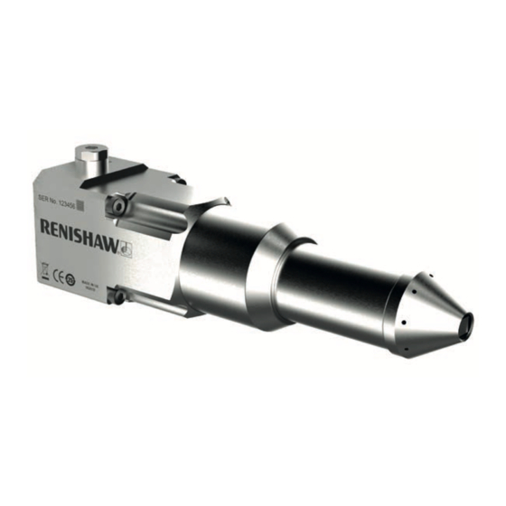
APC system Retract confirm sensor machine controller Cable (not supplied) interface unit HSI-C interface unit Cable (not supplied) Introduction The APC is typically used when the probe is mounted in a harsh environment; for example, The automatic probe cover (APC) is a tool setting where exposed to large pieces of flying swarf, or probe that features a pneumatically-operated long strands of swarf wrapping around the stylus... -
Page 16: Apc Probe Family
APC system (continued) APC probe family NOTE: A retract confirm sensor provides the The APC family of tool setting probes currently machine controller with a signal to indicate that consists of: the APC cover is retracted. • APCA air extension and air retraction •... -
Page 17: Interface Unit
Interface unit HSI-C interface unit HSI interface unit Introduction In addition to the features of the HSI, the HSI-C enables the user to select a suitable level of An HSI or HSI-C interface unit is required to immunity to false triggering (caused by machine convert the signals from the APC unit into vibrations or accelerations) for the connected voltage-free solid-state relay (SSR) outputs for... -
Page 18: Installing The Interface Unit
Installing the interface unit Install and configure the interface unit as described in the HSI hard-wired system interface installation guide (Renishaw part no. H-5500-8554), or the HSI-C hard-wired system interface – configurable installation guide (Renishaw part no. H-6527-8501). -
Page 19: Specification
Specification Principle application Tool setting probe with automatic protection cover for lathes and multi-tasking machines. Contamination management available with “air bleed”. Dimensions Length 189.4 mm (7.46 in) extended Width 45.0 mm (1.77 in) Depth 48.25 mm (1.90 in) Transmission type Hard-wired transmission Compatible interfaces HSI or HSI-C Weight... - Page 20 Specification (continued) Output connection Blanked DIN EN ISO 228–G 1/8 outlet for customer configurable “air blast stalk”. Mounting M4 × 50 mm (1.97 in) long (ISO 4762 grade 12.9) or equivalent × 4 Retract confirm sensor Operating voltage 12 Vdc to 30 Vdc, no load current 3 mA, rated operating current 150 mA, output resistance open collector, switching output PNP normally open (NO).
-
Page 21: Dimensions
Dimensions 189.4 (7.46) extended 188.5 (7.42) end of stylus 143.5 (5.65) retracted ±1° angular adjustment 41 (1.61) 9 (0.35) 12 (0.47) 3.5° è 3.5° 6 (0.24) 1.1 (0.04) mounting face 0.9 (0.04) 1.5 (0.06) sealing gasket compression 0.9 (0.04) Ø14 (Ø0.55) View on arrow A Stylus overtravel limits... -
Page 22: Preparing The Machine For Apc Installation
Preparing the machine for APC installation Introduction CAUTION: The APC is designed to be mounted horizontally or at any angle between horizontal The APC is designed to be mounted to a suitable and vertical with the nose cone facing down. It machine bulkhead, surface bulkhead or panel, must NOT be mounted with the nose cone at any and requires through holes to fix it in place. -
Page 23: Acceptable Orientation Of The Apc
Preparing the machine for APC installation (continued) Acceptable orientation of the APC Recommended... -
Page 24: Connecting The Apc To An Hsi Interface And The Cnc
Connecting the APC to an HSI interface and the CNC HSI interface Machine tool NOTES: Standard probe connector (3-way) When the APC is not being used, 1 Probe Input + it is recommended that the inhibit 2 Probe Input – function is enabled. -
Page 25: Connecting The Apc To An Hsi-C Interface And The Cnc
Connecting the APC to an HSI-C interface and the CNC HSI-C interface Standard probe connector (3-way) NOTES: When the APC is not being used, Machine tool it is recommended that the inhibit Block 4 17 Screen function is enabled. The retract confirm output could be used to 16 Probe Input + set the inhibit function (for more... -
Page 26: Probe Inhibit Function
Probe inhibit function The probe inhibit function is used to switch off the probe and can be deactivated by using the retract confirm output. HSI interface (controller connector) 1. Supply 12 V – 30 V 2. Retract confirm output 4. Probe + 2. -
Page 27: Pneumatic Set-Up
Pneumatic set-up Introduction It is also recommended to activate “air bleed” momentarily when the cover is retracted prior to The APC is a pneumatically operated probe cover measurement. that is available in two main configurations: A flow control valve can be fitted to regulate the •... -
Page 28: Logic Table Apca
Pneumatic set-up (continued) Logic table APCA Pressure Pressure Pressure Pressure Port 1 0 bar 0 bar >4.5 bar (65.3 psi) >4.5 bar (65.3 psi) Port 3 0 bar >4.5 bar (65.3 psi) 0 bar >4.5 bar (65.3 psi) Cover Unknown Extend Retract Extend “Air bleed” Logic table APCS Pressure Pressure Port 1... -
Page 29: Position Monitoring
This is confirmed by the retract confirm sensor. Monitor while measuring. NOTE: Air blast stalk not provided by Renishaw. Mechanical protection To protect the probe and APC mechanics it is Typical air blast stalk... -
Page 30: Apca With "Air Bleed" (Circuit 1)
Pneumatic set-up (continued) APCA with “air bleed” (circuit 1) The following pneumatic circuits are provided as examples of possible implementations of APC control. Bulkhead... -
Page 31: Operation Sequence (Circuit 1)
Pneumatic set-up (continued) Operation sequence (circuit 1) NOTE: V2 cannot be a pilot assisted valve. Operation Stylus Solenoid Solenoid Solenoid End of Monitor Variable Comment sequence valve 1 valve 2 valve 3 sequence to set (V1) (V2) (V3) trigger 1 Cover extend Protected Pressure switch Pressure activation... -
Page 32: Apca With "Air Bleed" (Circuit 2)
Pneumatic set-up (continued) APCA with “air bleed” (circuit 2) Bulkhead... -
Page 33: Operation Sequence (Circuit 2)
Pneumatic set-up (continued) Operation sequence (circuit 2) Operation Stylus Solenoid Solenoid Solenoid End of Monitor Variable Comment sequence valve 1 valve 2 valve 3 sequence to set (V1) (V2) (V3) trigger 1 Cover extend Protected Pressure switch Pressure activation switch 2 “Air bleed”... -
Page 34: Apcs With "Air Bleed" (Circuit 3)
Pneumatic set-up (continued) APCS with “air bleed” (circuit 3) Bulkhead... -
Page 35: Operation Sequence (Circuit 3)
Pneumatic set-up (continued) Operation sequence (circuit 3) Operation Stylus Solenoid Solenoid End of sequence Monitor Variable to Comment sequence valve 1 valve 2 trigger 1 Cover extend Protected Pressure switch Pressure Default state activation switch 2 “Air bleed” off Protected Time Pressure Sequence... -
Page 36: Apcs With No "Air Bleed" (Circuit 4)
Pneumatic set-up (continued) APCS with no “air bleed” (circuit 4) Bulkhead Operation sequence (circuit 4) Operation Stylus Solenoid End of sequence trigger Monitor Variable to sequence valve 1 Cover extend Protected Pressure switch activation Pressure Time switch 2 Cover retract Accessible Retract sensor Retract... -
Page 37: Installation
Installation * M4 x 50 mm (1.97 in) screws × 4 2.60 Nm to 2.70 Nm (1.92 lbf.ft to 1.99 lbf.ft) Ø4 mm (0.16 in) air pipes × 3 Air blast outlet (for customer implementation) M12 connector NOTE: The minimum bend radius of the cable is 25 mm (0.98 in) Seal Ø... -
Page 38: Best Practises - Pneumatics
Installation Best practices – pneumatics • Before connecting the air pipe to the inlet of the APC unit, briefly switch on the air supply to clear out any debris from the pipe. When WARNING: Before installing the pneumatics, no more debris is emitted, switch off the air ensure that the machine is safe to work on by supply and connect to the APC. -
Page 39: Pneumatic Connection
Installation (continued) Pneumatic connection Mounting the APC to the machine Mount the APC to fitting location using Connect the two standard and one optional 4 × M4 screws (supplied). Leave the screws Ø4.0 mm (0.16 in) air pipes to the connectors on semi-tight. the back of the unit (see “Installation”... -
Page 40: Fitting The Stylus
Installation (continued) Fitting the stylus Fully insert the stylus in place and rotate so the side face is approximately parallel to the Ensure the APC Cover is retracted. machine datums. Unscrew by hand, and remove the APC Secure with 2 × M3 grub screws (supplied) nose cone so the stylus mounting position is and torque to between 0.65 Nm and 0.70 Nm accessible. -
Page 41: Stylus Alignment
Stylus alignment Adjusting stylus to align with Adjust the alignment, starting with the axis with greatest angular error. machine axis As shown below, the adjusting screws are Check angular misalignment across the used to align the axes and secure the APC front face of the cube in both X and Y (top into position. - Page 42 Stylus alignment (continued) When the stylus has been adjusted to the Check perpendicularity and repeat until desired setting, check that all four adjusting desired setting is achieved. screws are torque tightened to between Fit the nose cone and hand tighten until fully 2.60 Nm and 2.70 Nm (1.92 lbf.ft and secure.
-
Page 43: Operating Procedure
Operating procedure To operate the APC Operating the probe cover is dependent on model and functionality. Refer to the appropriate logic table on page 14. NOTE: A retract confirm sensor provides the machine controller with a signal to indicate that the APC cover is retracted. -
Page 44: Service And Maintenance
Service and maintenance Service Maintenance You may undertake the maintenance routines WARNING: Compressed air can cause physical described in these instructions. injuries. Equipment requiring repair, overhaul or attention under warranty should be returned to your CAUTION: The APC is a precision tool and must supplier. -
Page 45: Cleaning Instructions
Service and maintenance (continued) Cleaning instructions Unscrew by hand, and remove the APC nose cone. Clean the inside of the APC and the nose cone to remove all the residue swarf or other debris. Refer to the diagram opposite and use a soft brush and low pressure coolant jet. -
Page 46: Fault-Finding
Perform health check on machine. to loose encoders, backlash, tight slideways and/or accidental damage. No probe Wiring fault. Check wiring. output. Probe has failed. Return APC to Renishaw for service. “Air bleed” “Air bleed” supply not connected or Check air connections. not working. faulty. - Page 47 Faulty air supply or swarf build up inside Check air supply. extending or or outside the APC. Clean the APC (see “Cleaning retracting instructions” on page 31). APCS cover Spring is faulty. Return APCS to Renishaw for service. not retracting.
-
Page 48: Parts List
Parts list Type Part number Description APCA A-6596-0001 APCA system, dual air with standard probe mechanism, installation and user’s guide and packaging. APCS A-6596-0002 APCS system, air extension and spring retraction with standard probe mechanism, installation and user’s guide and packaging. Stylus A-6560-7584 Length 59.25 mm (2.33 in), diameter 3 mm (0.12 in). - Page 49 Parts list (continued) Type Part number Description Publications. These can be downloaded from our web site at www.renishaw.com. H-5500-8554 Installation guide for HSI. HSI-C H-6527-8501 Installation guide for HSI-C.
- Page 52 Renishaw plc +44 (0)1453 524524 +44 (0)1453 524901 New Mills, Wotton-under-Edge uk@renishaw.com Gloucestershire, GL12 8JR United Kingdom www.renishaw.com For worldwide contact details, visit www.renishaw.com/contact *H-6596-8500-03*...
Need help?
Do you have a question about the APCA Series and is the answer not in the manual?
Questions and answers